Roof block filling hydraulic support and using method thereof

A technology of hydraulic supports and blocks, which is applied to mine roof supports, fillings, earthwork drilling and mining, etc. It can solve the problems of high labor intensity, difficulty in following machine operations, and low filling efficiency, and achieves obvious rock formation control effects and easy operation. Convenience, effect of reducing handling work

Active Publication Date: 2021-02-12
TAIYUAN UNIV OF TECH
View PDF8 Cites 0 Cited by
  • Summary
  • Abstract
  • Description
  • Claims
  • Application Information

AI Technical Summary

Problems solved by technology

The filling bag needs to be hung on the hydraulic support for paste filling, and a "separation wall" needs to be set up between the filling area and the unfilled area. The filling efficiency is low and it is difficult to follow the machine.
The general block filling method needs to make blocks in a specific chamber, and then transport them to the filling site for filling. The labor intensity of workers is high and the efficiency is low.

Method used


Image

  • Roof block filling hydraulic support and using method thereof
  • Roof block filling hydraulic support and using method thereof
  • Roof block filling hydraulic support and using method thereof

Examples


Embodiment 1

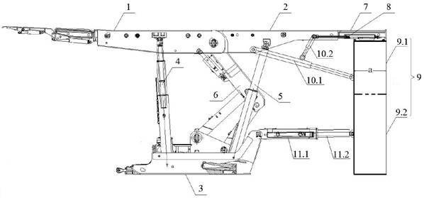
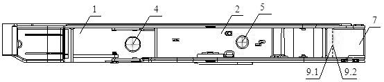
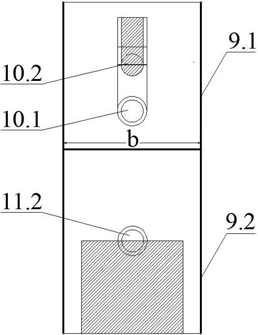
[0025] This embodiment provides a jacking block filling hydraulic support, including a support body; the support body includes a front roof beam 1, a rear roof beam 2 hinged with the front roof beam, and a The base 3, the front column 4 whose two ends are respectively hinged on the front roof beam 1 and the base 3, the rear column 5 whose two ends are respectively hinged on the rear roof beam 2 and the base 3, and the front column 4 and the rear column 5 are arranged between The four-bar linkage mechanism 6 is equipped with a telescopic beam 7 at the tail of the rear top beam 2, and the telescopic beam jack 8 inside the telescopic beam 7 protrudes from the telescopic beam 7 to connect with the rear top beam 2, and a filling and pouring mold is provided under the telescopic beam 7 9. The filling and pouring mold 9 includes an upper mold 9.1 located below the telescopic beam 7 and a lower mold 9.2 slidingly connected with the upper mold 9.1; both the upper mold 9.1 and the lower ...

Embodiment 2

[0034] This embodiment provides a method for using the roof block filling hydraulic support described in Embodiment 1, which includes the following steps:

[0035] S1, after the cut hole layout of the working face is completed, install the roof block filling hydraulic support, put the filling casting mold 9 close to the coal wall, and the telescopic beam 7 is in the retracted state (that is, the telescopic beam 7 is retracted into the top beam 2 at this time) , the mold height adjustment device swings upwards to drive the upper mold 9.1 to forcibly connect with the top plate to form a block pouring space;

[0036] S2, conveying the pouring material into the filling pouring mold 9 through the pouring pipeline, and performing the block pouring operation;

[0037] S3, after the blocks in the filling and pouring mold 9 are solidified to reach the preset strength, the mold pushing device pulls out the filling and pouring mold 9, moves and demoulds, and controls the moving step of the...


PUM


Abstract

The invention provides a jacking block filling hydraulic support and a method for using the same, belonging to the technical field of hydraulic supports. The roofing block filling hydraulic support includes a support body; the support body includes a front top beam, a rear top beam, a base, two The front columns are respectively hinged on the front roof beam and the base, the rear columns are respectively hinged on the rear roof beam and the base, and the four-bar linkage mechanism is arranged between the front column and the rear column. There is a telescopic beam, and the telescopic beam jack inside the telescopic beam protrudes from the telescopic beam to the back top beam, and a filling casting mold is arranged under the telescopic beam; a mold height adjustment device and a mold pushing device are arranged between the filling casting mold and the bracket body. The blocks of the hydraulic support have short solidification time, high strength and good roofing effect, continuous blocks, no need to manually set up "separation walls", high filling efficiency, and can realize follow-up operation, safe and efficient mining.

Description

technical field [0001] The invention belongs to the technical field of hydraulic supports, and specifically discloses a roofing block filling hydraulic support and a method for using the same. Background technique [0002] With the increasing demand for coal resources in our country, the problem of "three undercuts" of coal pressing has become increasingly prominent. The filling coal mining method is a green mining method developed for the "three undercuts" of coal pressing, surface subsidence, coal gangue discharge and land resources. One of the coal technologies. The backfill mining method is a rock formation control method for filling the goaf of the coal mining face with filling materials. At present, the main backfill mining methods include bulk backfill, paste backfill and block backfill. Although the hydraulic support for bulk filling has a tamping mechanism to make the bulk compactly filled, the filling rate of the goaf is low due to the large void ratio of the bulk...

Claims


Application Information

Patent Timeline
Patent Type & Authority Patents(China)
IPC IPC(8): E21D23/04E21F15/02
CPCE21D23/04E21F15/02
Inventor 朱德福宋选民李昊城霍昱名杨小兵加麦生
Owner TAIYUAN UNIV OF TECH
Why Eureka
Try Eureka