
Motor end cover automatic press-fitting device

A technology of pressing device and motor end cover, which is applied in metal processing, metal processing equipment, manufacturing tools, etc., can solve the problems of high end cover rejection rate, troublesome manual operation, and inability to press the end cover.

Active Publication Date: 2019-07-12
杭州烽银电机制造有限公司
View PDF12 Cites 4 Cited by
  • Summary
  • Abstract
  • Description
  • Claims
  • Application Information

AI Technical Summary

Problems solved by technology

[0002] In the assembly of the motor, the bearing and the end cover of the motor need to be press-fitted. At present, the assembly worker usually performs the press-fitting of the bearing and the end cover through the press-fitting tool. Manual operation is very troublesome for the feeding, loading and unloading of the motor end cover
[0003] Some existing automatic press-fitting equipment still requires workers to manually load materials when they are in use. Although a part of the workload is reduced, workers still need to stand by the side all the time to carry out material loading, which increases labor costs.
Moreover, some existing automatic press-fitting equipment cannot accurately press the end caps, so that the scrap rate of the end caps is high and wastes resources.

Method used


Image

  • Motor end cover automatic press-fitting device
  • Motor end cover automatic press-fitting device
  • Motor end cover automatic press-fitting device

Examples


Embodiment Construction

[0030] The following descriptions are only preferred implementations of the present invention, and the scope of protection is not limited to this embodiment. All technical solutions under the idea of ​​the present invention shall belong to the scope of protection of the present invention. At the same time, it should be pointed out that for those skilled in the art, some improvements and modifications without departing from the principle of the present invention should also be regarded as the protection scope of the present invention.

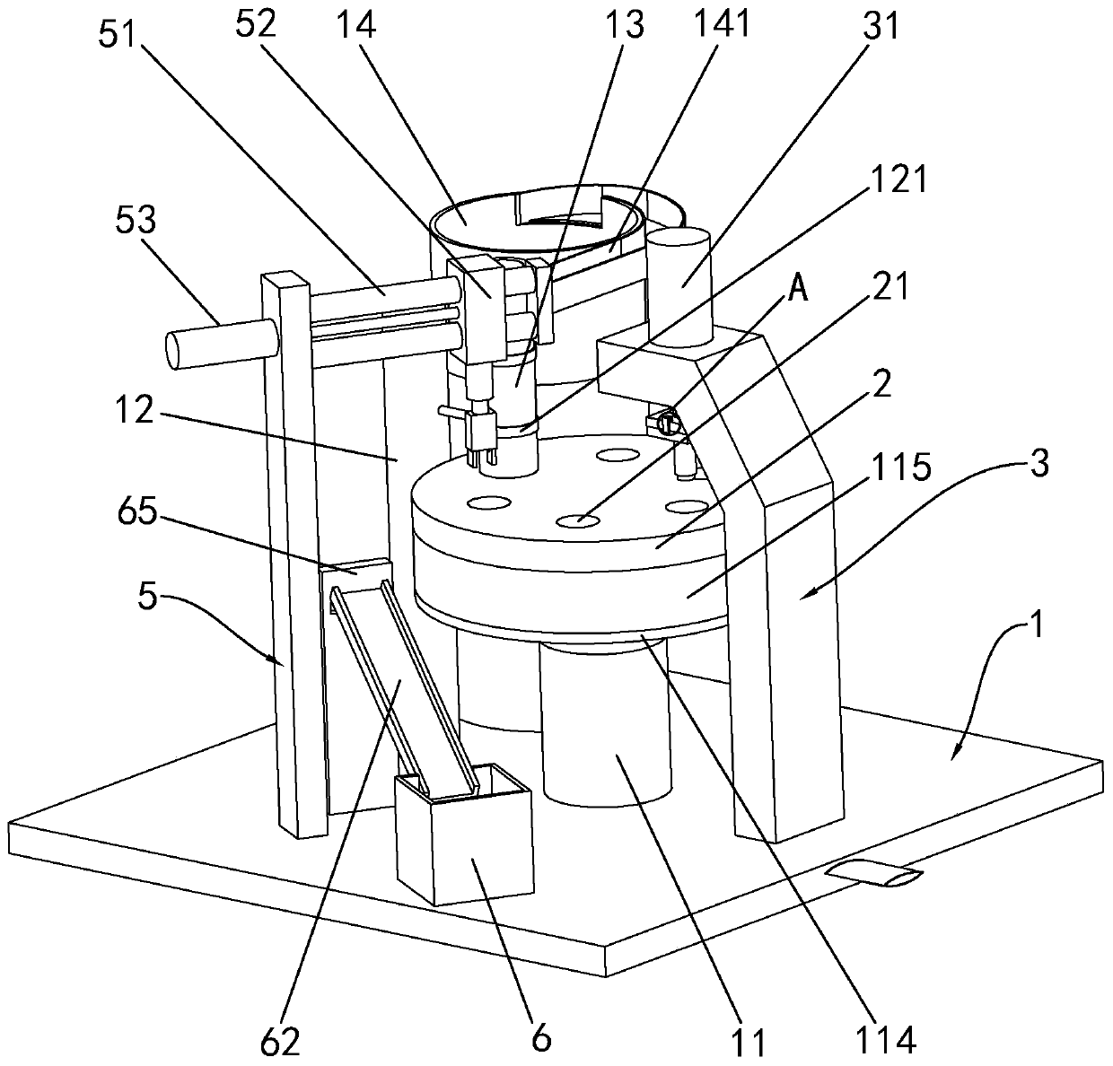
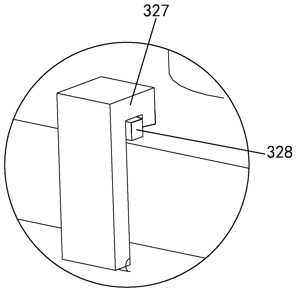
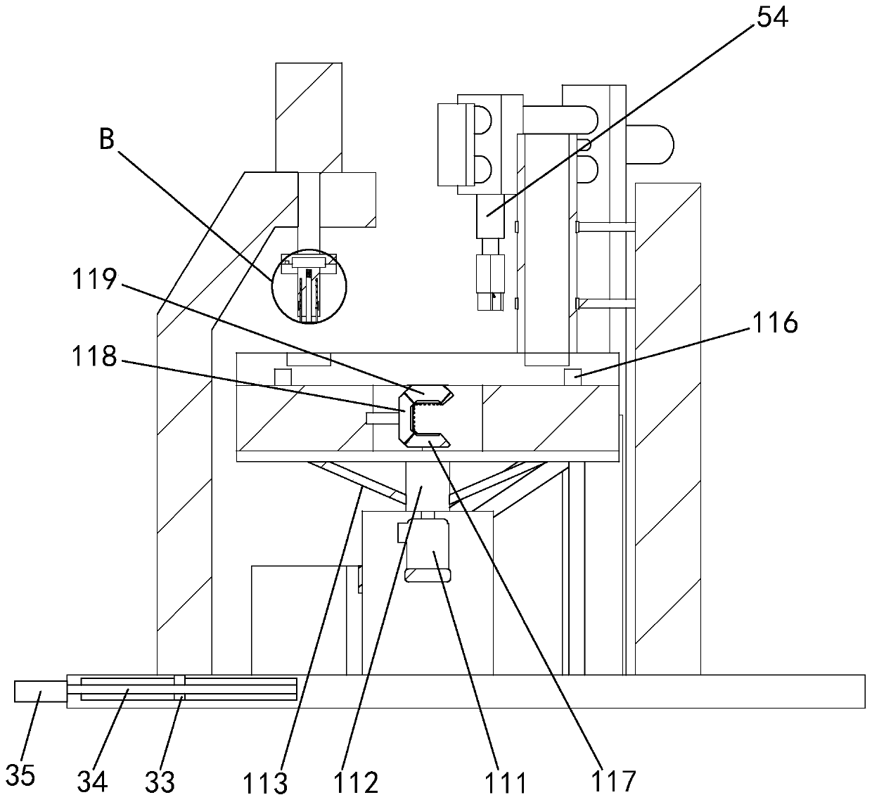
[0031] Such as figure 1 and image 3 As shown, an automatic pressing device for a motor end cover includes a base 1, the upper end surface of the base 1 is fixed with a column 11, the upper end surface of the column 11 is provided with a circulation plate 2, and the upper end surface of the circulation plate 2 is provided with six Solid material tank 21. The column 11 is embedded with a motor one 111, and the output shaft of the motor one 111 ...


PUM


Abstract

The invention discloses a motor end cover automatic press-fitting device. The motor end cover automatic press-fitting device comprises a base. A stand column is fixedly arranged on the upper end faceof the base. A rotary plate is arranged on the upper end face of the stand column. A main supporting frame is arranged on the base. The upper end of the main supporting frame is provided with a hydraulic cylinder. An auxiliary supporting frame is arranged on one side of the main supporting frame. The auxiliary supporting frame is provided with two guide rolls. A guide block is arranged on the guide rolls. The guide block is provided with a cylinder I. An output shaft of the cylinder I is connected with a material fixing block. The lower end of the material fixing block is provided with two clamping arms. A feed barrel is arranged on the base. The base is fixedly provided with a vibration tray. One side of the vibration tray is provided with a discharge passage. One end of the discharge passage is fixedly connected with the feed barrel. The motor end cover automatic press-fitting device is reasonable in structure and conveys an end cover in the vibration tray onto the rotary plate. Thehydraulic cylinder is started to conduct press-fitting on the end cover. The end cover subjected to press-fitting is clamped by the two clamping arms and is moved out from the rotary plate. Thus, themotor end cover automatic press-fitting device achieves the automatic press-fitting effect on the end cover.

Description

technical field [0001] The invention relates to the field of motor component assembly, in particular to an automatic pressing device for a motor end cover. Background technique [0002] In the assembly of the motor, the bearing and the end cover of the motor need to be press-fitted. At present, the assembly worker usually performs the press-fitting of the bearing and the end cover through the press-fitting tool. It is very troublesome to manually operate the feeding, loading and unloading of the motor end cover. [0003] Some existing automated press-fitting equipment still require workers to manually load materials when they are in use. Although a part of the workload is reduced, workers still need to stand by the side all the time to carry out material loading, which increases labor costs. Moreover, some existing automatic press-fitting equipment cannot press and fit the end caps very accurately, so that the scrap rate of the end caps is high and resources are wasted. Ai...

Claims


Application Information

Patent Timeline
IPC IPC(8): B23P19/00B23P19/02
CPCB23P19/001B23P19/02
Inventor 曹柯锋
Owner 杭州烽银电机制造有限公司
Learn More