Modeling method of temperature and pressure reducing device

A technology of temperature reduction and decompression and modeling method, which is applied in special data processing applications, instruments, electrical digital data processing, etc., and can solve problems such as the difficulty of applying momentum equation integration, steam state fluctuations, and time-consuming simulation calculations.

Active Publication Date: 2019-07-09
NO 719 RES INST CHINA SHIPBUILDING IND
View PDF2 Cites 0 Cited by
  • Summary
  • Abstract
  • Description
  • Claims
  • Application Information

AI Technical Summary

Problems solved by technology

During operation, the steam is throttled and decompressed. As the flow rate changes, its dynamic working process is extremely complicated, and at the same time, it will cause large fluctuations in the steam state after decompression and decompression.
At present, the mathematical physical model of the dynamic process of the desuperheater and pressure reducer is very complicated. If the corresponding momentum and energy equations are established for the volumes of each stage, it will be difficult to apply the integral of the momentum equation because the pressure in the flow is unknown along the surface function, resulting in In the overall simulation of the nuclear power plant, the model establishment of the temperature and pressure reduction device is very cumbersome, which increases the difficulty of the iterative design of the steam discharge system and related systems. error, thereby affecting the overall design schedule of the nuclear power plant

Method used


Image

  • Modeling method of temperature and pressure reducing device
  • Modeling method of temperature and pressure reducing device
  • Modeling method of temperature and pressure reducing device

Examples


Embodiment Construction

[0013] The present invention will be further described in detail below in conjunction with the accompanying drawings and specific embodiments.

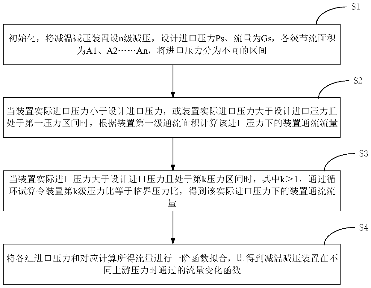
[0014] Such as figure 1 As shown, the modeling method of the temperature and pressure reduction device of the present invention includes:

[0015] S1, initialization

[0016] S1.1. The temperature and pressure reduction devices are set up with n stages of pressure reduction, and the design inlet pressure is P s , design flow G s , the throttling area of ​​each stage is A 1 、A 2 ...A n ;

[0017] S1.2. Divide the inlet pressure into different intervals, respectively χ 1 =(0MPa,3.9MPa], χ 2 =(3.9MPa,5MPa], χ 3 =(5MPa,6.1MPa], χ 4 =(6.1MPa,7.2MPa],......χ k =(P k-min ,p k-max ], the division of the pressure range is based on the following: the decompression process at all levels should be an isenthalpic process, and the value of the inlet pressure of the device P k-max It should be possible to make the saturated steam entha...


PUM


Abstract

The invention relates to a modeling method of a temperature and pressure reducing device. The method comprises the following steps: S1, initializing; S2, when the actual inlet pressure of the device is smaller than the designed inlet pressure or the actual inlet pressure of the device is larger than the designed inlet pressure and located in a first pressure interval, calculating the device through-flow flow under the inlet pressure according to the first-stage through-flow area of the device; S3, when the actual inlet pressure of the device is larger than the designed inlet pressure and is inthe kth pressure interval with larger than 1, enabling the kth pressure ratio of the device to be equal to the critical pressure ratio through cyclic trial calculation, and the through-flow flow flow of the device under the actual inlet pressure is obtained; and S4, carrying out first-order function fitting on each group of inlet pressure and the correspondingly calculated flow to obtain a flowchange function passed by the temperature and pressure reduction device under different upstream pressures. The flow change function of the temperature and pressure reduction device under different upstream pressures can be obtained, and the flow change function is suitable for being used as the input for establishing the simulation model of the nuclear power device steam discharge system.

Description

technical field [0001] The invention relates to modeling of a temperature and pressure reduction device, in particular to a modeling method for a temperature and pressure reduction device in a steam discharge system of a nuclear power plant. Background technique [0002] The temperature and pressure reduction device is an important device used to adjust steam pressure and temperature. It is widely used in industrial production and is also the key equipment of the steam discharge system in marine nuclear power plants. The steam discharge system is an essential system for marine nuclear power plants, and it is used to ensure the safe operation of nuclear power plants. Therefore, mastering the characteristics of the dynamic operation of the desuperheating and decompression device is the key to the stable operation of the entire steam discharge system. [0003] The temperature and pressure reduction device is equipped with throttle plates at various levels, and the high-tempera...

Claims


Application Information

Patent Timeline
Patent Type & Authority Applications(China)
IPC IPC(8): G06F17/50
CPCG06F30/20G06F2119/08
Inventor 罗小雨刘现星方园程堃孙海军
Owner NO 719 RES INST CHINA SHIPBUILDING IND
Why Eureka
Try Eureka