
Reflective liquid crystal display panel

A liquid crystal display panel, reflective technology, applied in nonlinear optics, instruments, optics, etc., can solve the problems of weak display quality effect, affect display effect, reduce product quality, etc., and achieve the effect of low display power consumption and product cost

Inactive Publication Date: 2019-07-05
SHENZHEN CHINA STAR OPTOELECTRONICS TECH CO LTD
View PDF9 Cites 4 Cited by
  • Summary
  • Abstract
  • Description
  • Claims
  • Application Information

AI Technical Summary

Problems solved by technology

Since the transmissive liquid crystal display device is provided with light for display by the backlight source, it has the characteristics of excellent display ability in weak light or no light environment, but in a strong light environment (such as outdoor sunlight), the transmissive liquid crystal display device often There is the problem of insufficient brightness of the backlight, which seriously affects the display effect. At this time, if the brightness of the backlight of the backlight is simply increased, not only the effect of improving the display quality of the transmissive liquid crystal display device is weak, but also due to the increase of the brightness of the backlight, It will greatly increase the power consumption of the liquid crystal display device and reduce the quality of the product

Method used


Image

  • Reflective liquid crystal display panel
  • Reflective liquid crystal display panel
  • Reflective liquid crystal display panel

Examples


Embodiment Construction

[0025] In order to further illustrate the technical means adopted by the present invention and its effects, a detailed description is given below in conjunction with the preferred embodiments of the present invention and the accompanying drawings.

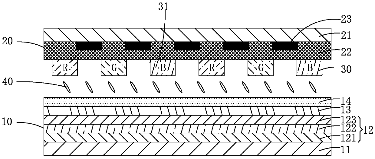
[0026] see figure 1 , the reflective liquid crystal display panel according to the first embodiment of the present invention includes a TFT array substrate 10 and an opposite substrate 20 arranged oppositely. The TFT array substrate 10 includes a first substrate 11 , a TFT array layer 12 , a passivation layer 13 and a pixel electrode layer 14 which are arranged in sequence along a direction close to the opposite substrate 20 . The opposite substrate 20 includes a second substrate 21 and a light-reflecting common electrode layer 22 disposed in sequence along a direction close to the TFT array substrate 10 . The opposite substrate 20 is provided with a color filter layer 30 on the side of the common electrode layer 22 close to the T...


PUM


Abstract

The invention provides a reflective liquid crystal display panel comprising a TFT array base plate and an opposite base plate arranged oppositely; the TFT array base plate comprises a first substrate,a TFT array layer, a passivation layer and a pixel electrode layer sequentially arranged along a direction close to the opposite base plate; the opposite base plate comprises a second substrate and areflective common electrode layer sequentially arranged along a direction close to the TFT array base plate; the opposite base plate is provided with a colored filter layer arranged on one side, close to the TFT array base plate, of the common electrode layer, or the TFT array base plate is provided with a colored filter layer between the passivation layer and the pixel electrode layer, so that when the reflective liquid crystal display panel is working, the ambient light enters from one side of the TFT array base plate and exits from one side of the TFT array base plate for displaying afterbeing reflected by the reflective common electrode, the backlight source does not need to be arranged, and the display power consumption and the product cost are relatively low.

Description

technical field [0001] The present invention relates to the field of display technology, and in particular, to a reflective liquid crystal display panel. Background technique [0002] Liquid Crystal Display (LCD) has many advantages such as thin body, power saving, no radiation, etc., and has been widely used, such as: mobile phones, personal digital assistants (PDAs), digital cameras, computer screens and notebook computers screen etc. [0003] In the prior art, a liquid crystal display device generally includes a liquid crystal display panel. The liquid crystal display panel includes a color filter substrate (Color Filter Substrate) and a thin film transistor array substrate (Thin Film TransistorArray Substrate, TFT Array Substrate) arranged oppositely, and a liquid crystal layer (Liquid Crystal Layer) disposed between the color filter substrate and the TFT array substrate. Its working principle is to control the rotation of the liquid crystal molecules of the liquid cry...

Claims


Application Information

Patent Timeline
Patent Type & Authority Applications(China)
IPC IPC(8): G02F1/1343G02F1/1335
CPCG02F1/133514G02F1/133553G02F1/134309G02F1/13439
Inventor 田新斌徐向阳
Owner SHENZHEN CHINA STAR OPTOELECTRONICS TECH CO LTD
Learn More