
Test device for the sedimentation drag coefficients of drilling cutting particles

A technology of drag coefficient and particle settlement, which is applied in the direction of analyzing materials and instruments, can solve the problems that the shape description factor is too simplified, does not consider the direction of settlement, and cannot finely distinguish the shape of particles, so as to improve the prediction accuracy

Active Publication Date: 2019-06-28
SOUTHWEST PETROLEUM UNIV
View PDF12 Cites 4 Cited by
  • Summary
  • Abstract
  • Description
  • Claims
  • Application Information

AI Technical Summary

Problems solved by technology

Ganser (1993) proposed a method to predict the settlement drag coefficient of spherical and non-spherical, but did not consider the problem of settlement directionality
Gholamhossein Bagheri (2016) proposed a settling drag coefficient prediction model considering regular and irregular non-spherical particles, but the calculation of the shape description factor has the problem that the particle shape cannot be finely distinguished
Although Xianzhi Song (2017) considers the problem of settlement direction, there are oversimplification problems in the calculation of projected area and the use of shape description factors

Method used


Image

  • Test device for the sedimentation drag coefficients of drilling cutting particles
  • Test device for the sedimentation drag coefficients of drilling cutting particles
  • Test device for the sedimentation drag coefficients of drilling cutting particles

Examples


Embodiment Construction

[0035] The following will clearly and completely describe the technical solutions in the embodiments of the present invention in conjunction with the accompanying drawings in the embodiments of the present invention. Obviously, the described embodiment is only one embodiment of the present invention, not all embodiments . Based on the embodiments of the present invention, all other embodiments obtained by persons of ordinary skill in the art without making creative efforts belong to the protection scope of the present invention.

[0036] Such as figure 1 As shown, a test device for the settling drag coefficient of cuttings particles includes a simulated wellbore 1, a high-speed camera 2, a data collector 3 and a computer 4.

[0037] The simulated shaft 1 is a cylindrical structure with a closed bottom and an upper opening, made of transparent materials (such as glass, plastic), 1 meter high and 0.2 meters in diameter. The simulated wellbore 1 also includes a drain valve 5 lo...


PUM


Abstract

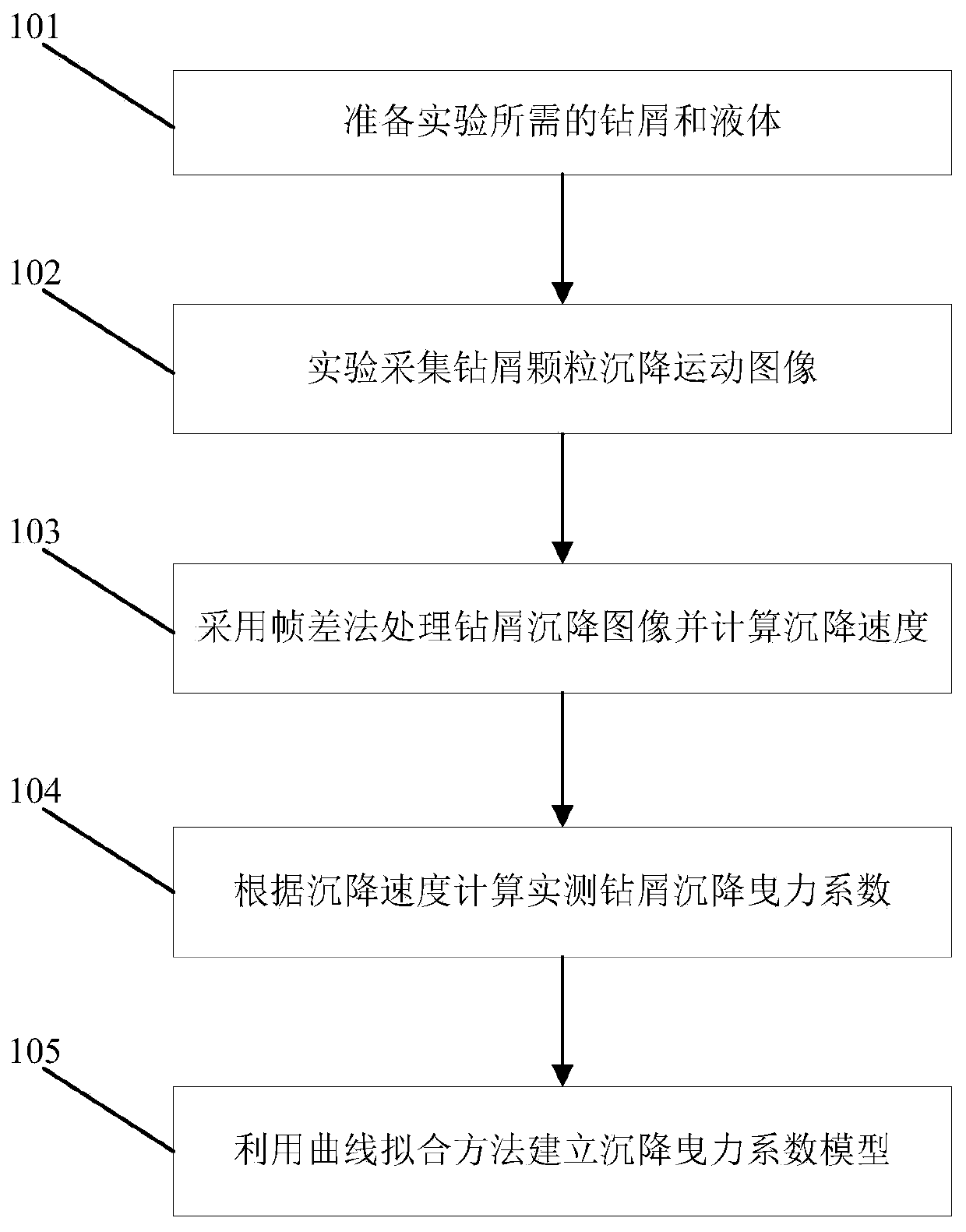
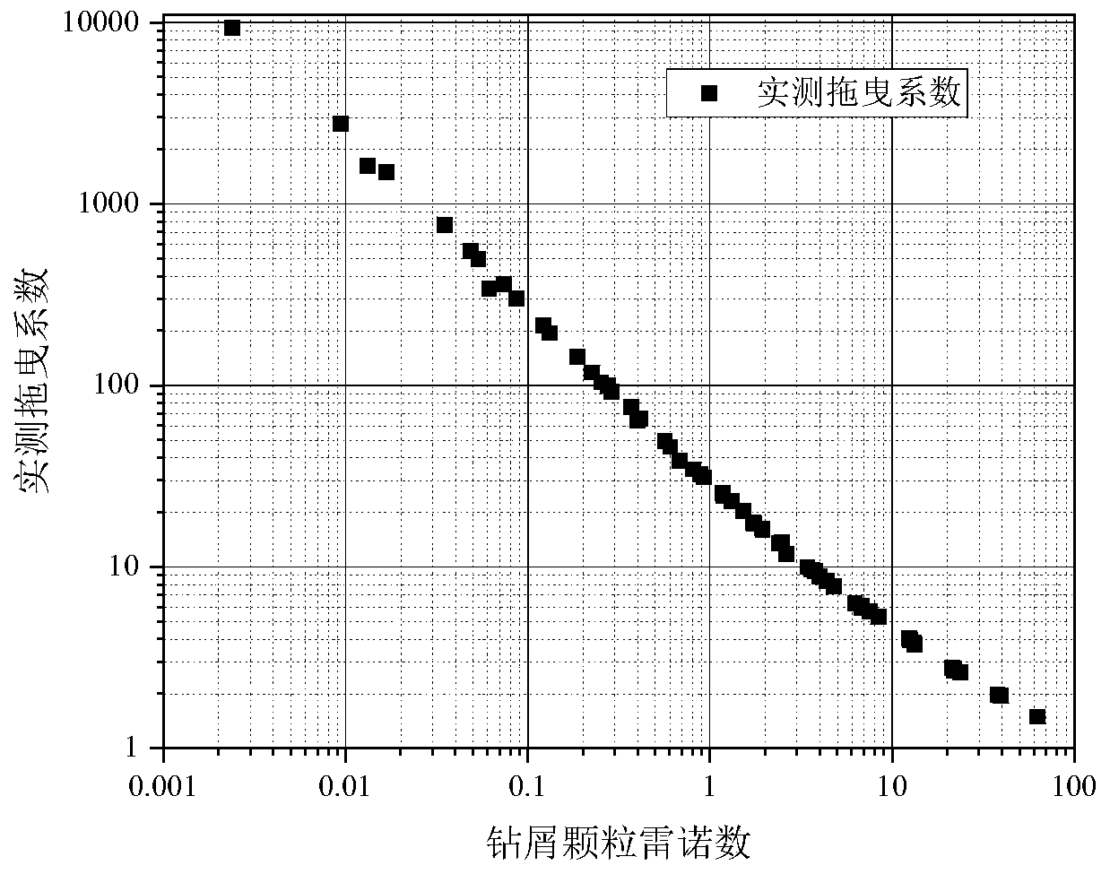
The invention discloses a test device for the sedimentation drag coefficients of drilling cutting particles. The test device comprises a simulated wellhole, a high speed camera, a data collector and acomputer. In addition, the test method comprises the following steps: step A, carrying out experimental preparation work, sorting experimental settlement drilling cuttings by using a screening net, injecting prepared liquid in a simulated wellhole, and carrying out standing to prevent bubble generation; step B, aligning the camera at the simulated wellhole, placing different mesh numbers of sorted drilling cutting particles in a liquid level slightly one by one, observing a sedimentation experiment of the drilling cutting particles in liquid, and collecting object sedimentation images; step C, processing the collected images and acquiring sedimentation speeds of the drilling cutting particles by using a frame difference method; step D, calculating a sedimentation drag coefficient based onthe sedimentation speeds obtained by the experiment; and step E, constructing a new shape description factor to obtain a new sedimentation drag coefficient empirical model. Therefore, the sedimentation drag coefficients of rock debris particles with different shapes can be analyzed deeply; and thus the prediction accuracy is improved.

Description

technical field [0001] The invention belongs to the technical field of oil and gas field development, in particular to a test device and method for the settling drag coefficient of drill cuttings particles. Background technique [0002] During the drilling process, wellbore cleaning is one of the main issues affecting efficient and safe drilling. The drilling cuttings in the wellbore are distributed in the drilling fluid in the form of particles. The drilling fluid is a continuous phase and the cuttings are a discontinuous phase, and the cuttings are carried out of the wellbore by the drilling fluid. When the drilling fluid is not enough to provide enough energy to move the cuttings, a cuttings bed will be formed at the bottom of the well. The formation of the cuttings bed will increase the annular pressure loss, which will easily cause high torque and high resistance of the drill string. Adhesion sticking causes problems such as difficulty in running casing and cementing,...

Claims


Application Information

Patent Timeline
IPC IPC(8): G01N15/04G01N15/00
Inventor 王贵杜辉陈颖文杰蒲晓林李方
Owner SOUTHWEST PETROLEUM UNIV
Learn More