Road milling machine

A milling machine and ground technology, applied in the field of ground milling machines, can solve the problems of cumbersome transfer and so on

Pending Publication Date: 2019-06-21
BOMAG
View PDF5 Cites 1 Cited by
  • Summary
  • Abstract
  • Description
  • Claims
  • Application Information

AI Technical Summary

Problems solved by technology

In this milling operation, also known as inside milling, the operator of the ground milling machine is milling almost blind and has to work, for example, according to an area far in front of the ground milling machine in the working direction, or The shifting of the internally located reference to the zero side has to be realized beforehand in a cumbersome manner, for example by means of correspondingly spaced colored markings

Method used


Image

  • Road milling machine
  • Road milling machine
  • Road milling machine

Examples


Embodiment Construction

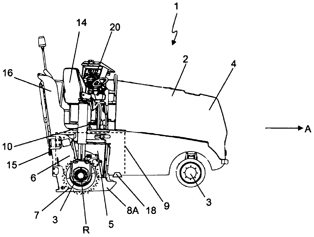
[0029] by Figure 1A The main elements of a ground milling machine 1 of the described type can be seen in the side view. In addition to the frame 2 , the ground milling machine 1 also includes: a traveling device 3 , such as a crawler mechanism or wheels; a drive motor 4 , specifically a diesel engine; a ground milling device 5 ; and a driving platform 10 . The traveling device 3 is connected to the frame 2, for example via lifting columns, so that the frame 2 is height-adjustable relative to the foundation. The drive energy required for the operation of the ground milling machine is provided by the drive motor 4 . During working mode, the ground milling machine 1 is operated by an operator on the operator's platform 10 . The ground milling machine 1 shown is in particular a so-called tail rotor milling machine, wherein the ground milling device 5 is arranged in the rear region of the ground milling machine 1 below the operator's cab 10 .

[0030] The ground is milled by mea...


PUM


Abstract

The application relates to a road milling machine (1) having a machine frame (2), driving devices (3) connected to the machine frame, a drive motor (4), a driver's station (10), and a road milling apparatus (5) comprising a road milling drum (7) and a milling drum box (6) surrounding the latter and having height-adjustable side shields (8A, 8I) which are arranged transversely to the rotation axis(R) of the road milling drum. An outer side shield (8A) terminates substantially flush with an outer side of the machine frame, and an inner side shield (8I) is offset towards the longitudinal center(M) of the machine from an opposite outer side. An essential concept of the application consists in that a viewing shaft (9) is present so that the inner side shield and / or a road area in front of theinner side shield in the working direction (A) is at least partially visible from the driver's station.

Description

technical field [0001] The invention relates to a ground milling machine. Background technique [0002] A ground milling machine of the type described comprises: a frame; traveling means connected to the frame, such as caterpillars or wheels; a drive motor, usually a diesel engine; a cab, from which the ground milling machine is operated; And a ground milling device comprising a milling roller and a milling roller box surrounding the milling roller. The milling roll box has height-adjustable side guards arranged transversely to the axis of rotation of the milling roll, the outer side guards being located substantially flush with the outer side of the machine frame, which is also referred to here as the zero side, On the other hand, the inner side guards are offset from the opposite outer side in the direction of the longitudinal center of the machine and are used, for example, to connect a drive transmission for the milling roller. The inner side guard is therefore not flu...

Claims


Application Information

Patent Timeline
Patent Type & Authority Applications(China)
IPC IPC(8): E01C23/088
CPCE01C23/088E01C2301/30
Inventor O·埃德尔曼
Owner BOMAG
Why Eureka
Try Eureka