
Comprehensive energy system risk identification method based on multi-energy flow fault coupling propagation

A comprehensive energy system and risk identification technology, applied in resources, data processing applications, instruments, etc., can solve problems such as ignoring pipeline failures, not many, and underestimating system operation risks

Inactive Publication Date: 2019-06-21
CHANGSHA UNIVERSITY OF SCIENCE AND TECHNOLOGY
View PDF1 Cites 7 Cited by
  • Summary
  • Abstract
  • Description
  • Claims
  • Application Information

AI Technical Summary

Problems solved by technology

[0004] Different from the more mature power system risk assessment, there are not many studies on the risk assessment of integrated energy systems at home and abroad: Among them, the research uses the Markov model to conduct a reliability analysis of small-scale cooling-heating-electricity cogeneration systems in buildings. Through quantitative analysis, the results show that the indicators of energy supply reliability have been greatly improved after cooling-heating-electricity cogeneration; for multi-energy microgrids with energy storage, two typical operating modes of grid-connected and isolated Reliability assessment model, however, a major feature of the existing methods is that they fail to consider the topology of the integrated energy system. The defect lies in ignoring the possible faults of the pipelines. In practice, the probability of pipeline failures is much greater than that of equipment. Probability of outages, resulting in an underestimated risk to system operation

Method used


Image

  • Comprehensive energy system risk identification method based on multi-energy flow fault coupling propagation
  • Comprehensive energy system risk identification method based on multi-energy flow fault coupling propagation
  • Comprehensive energy system risk identification method based on multi-energy flow fault coupling propagation

Examples


Embodiment Construction

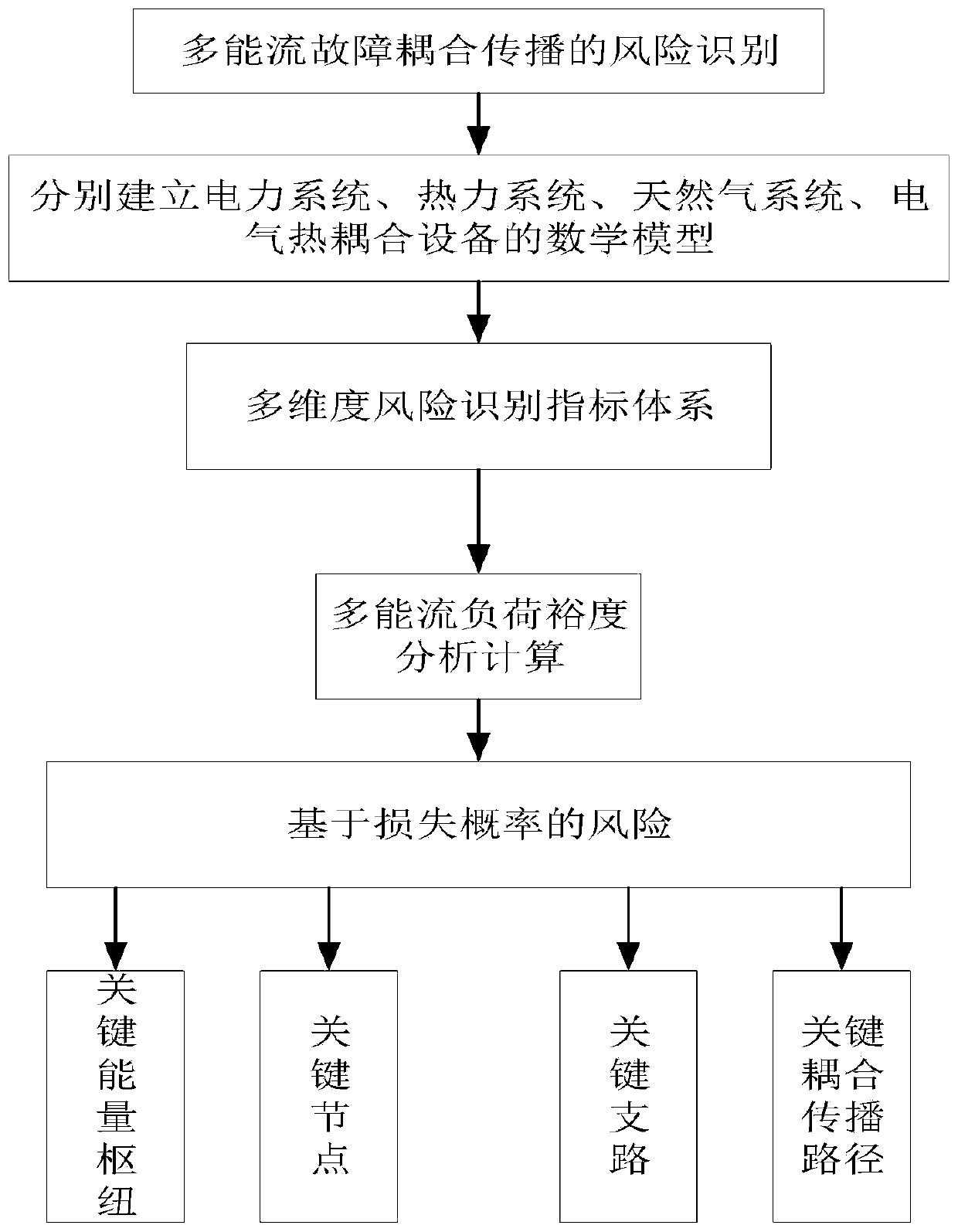
[0011] Step 1: Establish mathematical models of power system, thermal system, natural gas system, electrothermal coupling equipment, and electrical coupling equipment;

[0012] (1) Establish a mathematical model of the power system:

[0013]

[0014]

[0015] Among them, P i , Q i where is the active power and reactive power injected by the node; e i , f i Indicates the real and imaginary parts of the node voltage; G ij 、B ij are the real and imaginary parts of the corresponding elements of the nodal admittance matrix.

[0016] (2) Establish a mathematical model of the thermal system: the thermal system is composed of heat sources, heat networks and heat loads; the variables of the heat network include the pressure p of each node t , node injection traffic m υ , and pipeline flow m e , the relationship between each variable (Equation (3), (4) indicates that the steam flow into the node is equal to the steam flow out of the node plus the steam flow consumed by the...


PUM


Abstract

The invention discloses a comprehensive energy system risk identification method based on multi-energy flow fault coupling propagation, and relates to the field of comprehensive energy safety analysis, which comprises the following steps: 1) respectively establishing mathematical models of a power system, a thermodynamic system, a natural gas system and electric thermal coupling equipment; 2) designing a risk identification system: putting forward a multi-dimensional risk identification index system for the multi-energy type contained in the comprehensive energy system; 3) calculating and analyzing a load margin optimization model of the electric thermal coupling system by combining a comprehensive energy network power flow optimization algorithm; and 4) based on the risk of load margin loss probability, determining a key branch, a node, a coupling propagation path and a key energy hub for mutual conversion between heterogeneous energy flows of the energy transmission network in the comprehensiveenergy system. The invention provides a comprehensive energy system risk identification method based on multi-energy flow fault coupling propagation. The safety, flexibility and reliabilityof social energy supply are improved.

Description

technical field [0001] The invention relates to a comprehensive energy system risk identification method based on multi-energy flow fault coupling propagation, belonging to the field of comprehensive energy system safety analysis. Background technique [0002] Energy is the basis for the survival and development of human beings and the lifeblood of the national economy. How to reduce environmental pollution in the process of energy consumption while ensuring sustainable energy supply for human society is a common concern of all countries in the world today. Facing the dual challenges of resources and environment, many countries regard the integrated energy system (IES) as their future development strategy. IES breaks the original mode of independent design, planning, operation and control of cooling / heating / electricity / gas energy supply systems. Organic coordination and optimization of consumption and other links can improve the security, flexibility and reliability of soc...

Claims


Application Information

Patent Timeline
Patent Type & Authority Applications(China)
IPC IPC(8): G06Q10/06G06Q50/06
CPCY02P90/82
Inventor 马瑞
Owner CHANGSHA UNIVERSITY OF SCIENCE AND TECHNOLOGY
Learn More