
Wood processing machine tool capable of automatically pushing wood

A technology for processing machine tools and pushing mechanisms, which is applied to wood processing appliances, processing machines for manufacturing flat surfaces, and special forming/shaping machines. Achieve the effect of ingenious structure, reduced labor intensity and simple principle

Active Publication Date: 2019-06-21
日照市冠通木业有限公司
View PDF4 Cites 3 Cited by
  • Summary
  • Abstract
  • Description
  • Claims
  • Application Information

AI Technical Summary

Problems solved by technology

[0002] The woodworking planer is used to plan a reference plane or two perpendicular planes of the workpiece. The motor drives the planer shaft to rotate at a high speed. The workpiece is pressed by hand along the guide plate and close to the front table to feed the planer. The front table is lower than the rear table. The height difference is the thickness of the planing layer. During the use of the existing woodworking planer, the operator must press the wood workpiece and send it towards the planer. It has certain defects. On the one hand, the labor intensity of the operator is high, especially for On the other hand, a part of the planer is exposed between the front workbench and the rear workbench, which has buried hidden dangers for the safety of the operators. In order to solve the above-mentioned defects, the inventor has designed a clever, The principle is simple, time-saving and labor-saving, no need for operators to manually push the workpiece, a woodworking planer that automatically pushes wood with a high safety factor

Method used


Image

  • Wood processing machine tool capable of automatically pushing wood
  • Wood processing machine tool capable of automatically pushing wood
  • Wood processing machine tool capable of automatically pushing wood

Examples


Embodiment Construction

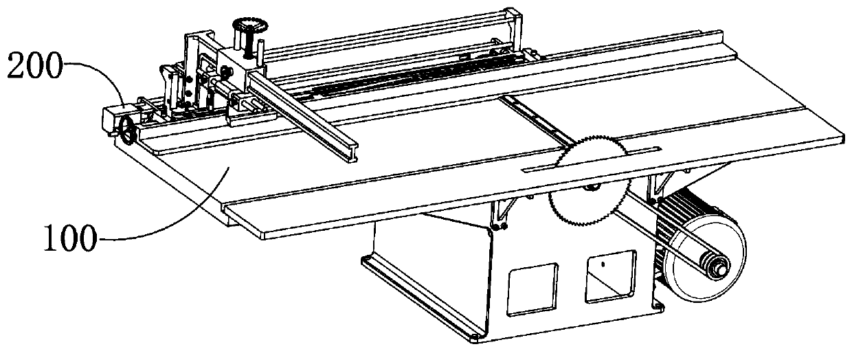
[0060] A wood processing machine tool that automatically pushes wood, which includes a planer body 100, a traveling drive device 200, and a retraction reset device 300. The planer body 100 includes a rectangular front panel 102 and a rear panel 103 arranged horizontally, and a bed arranged below the two The body 101 supports it, and a planing mechanism 110 is arranged between the front board 102 and the back board 103. An automatic pushing mechanism 130 is also movable, and the automatic pushing mechanism 130 is used to push the wood workpiece close to the front panel 102 and move to the back panel 103 after being planed by the planing mechanism 110. The driving device 200 is connected with the automatic pushing mechanism 130 and used In order to provide pushing power to the automatic pushing mechanism 130 , the retraction reset device 300 is used to cut off the power output of the traveling driving device 200 and control the traveling driving device 200 and the automatic pushi...


PUM


Abstract

The invention provides a wood processing machine tool capable of automatically pushing wood. The wood processing machine tool comprises a planer, a travelling driving device and a retracting reset device, the planer comprises a front platen and a rear platen which are rectangularly and horizontally arranged, and a planer body arranged on the lower part of the front platen and the lower part of therear platen supports the planer, a planing mechanism is arranged between the front platen and the rear platen, the height of the front platen is less than that of the rear platen and the height difference between the front platen and the rear platen is the thickness of a planing layer, an automatic push mechanism is further movably arranged on the planer, the automatic push mechanism is used forpushing wood workpieces to be tightly attached to the front platen and then move to the rear platen after being planed by the planing mechanism, the travelling driving device is connected with the automatic push mechanism and used for providing push power to the automatic push mechanism, and the retracting reset device is used for cutting off the power output of the traveling driving device and controlling the traveling driving device and the automatic push mechanism to reset automatically.

Description

technical field [0001] The invention relates to a woodworking planer, in particular to a wood processing machine tool for automatically pushing wood. Background technique [0002] The woodworking planer is used to plan a reference plane or two perpendicular planes of the workpiece. The motor drives the planer shaft to rotate at a high speed. The workpiece is pressed by hand along the guide plate and close to the front table to feed the planer. The front table is lower than the rear table. The height difference is the thickness of the planing layer. During the use of the existing woodworking planer, the operator must press the wood workpiece and send it towards the planer. It has certain defects. On the one hand, the labor intensity of the operator is high, especially for On the other hand, a part of the planer is exposed between the front workbench and the rear workbench, which has buried hidden dangers for the safety of the operators. In order to solve the above-mentioned d...

Claims


Application Information

Patent Timeline
Patent Type & Authority Applications(China)
IPC IPC(8): B27C9/02B27C1/02B27C1/12B27C1/14B27C5/02B27C5/06
Inventor 张红梅
Owner 日照市冠通木业有限公司
Learn More