A rocket engine flange rapid design system based on a visual interface
A rocket engine and design system technology, which is applied in computing, instrumentation, electrical and digital data processing, etc., can solve the problems of long design cycle and complex design process of rocket engine flanges, and achieves improving design work efficiency, lowering the threshold and shortening the design. effect of cycles
- Summary
- Abstract
- Description
- Claims
- Application Information
AI Technical Summary
Problems solved by technology
Method used
Image
Examples
specific Embodiment approach 1
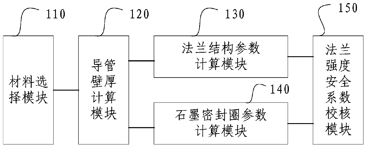
[0049] DETAILED DESCRIPTION OF THE PREFERRED EMBODIMENTS One, the first aspect of the present invention provides a rocket engine flange rapid design system based on a visual interface, the system obtains a visual interface based on VB programming, combined figure 1 shown, including:
[0050] The material selection module 110 is used to determine the material of the flange and the conduit according to the maximum pressure of the engine system and the inner diameter of the conduit at the maximum pressure;
[0051] The conduit wall thickness calculation module 120 is used to calculate and obtain the conduit wall thickness according to the conduit design safety factor;
[0052] The flange structure parameter calculation module 130 is used to calculate and obtain the initial flange structure parameters according to the wall thickness of the conduit;
[0053] The graphite sealing ring parameter calculation module 140 is used to calculate and obtain the parameters of the graphite seal...
Embodiment
[0106] Embodiment: the highest pressure of the engine system of the flange to be designed is 15MPa, the operating temperature is 110K, and the inner diameter of the conduit at the highest pressure is 80mm;
[0107] Use the material selection module to determine that flanges, bolts, and piping materials are all GH4169; and then through the metal material manual, it is determined that the yield limit of GH4169 is about 1080Mpa at a temperature of 110K; when n is 2 and μ is 0.8, the conduit can be calculated Wall thickness δ i for:
[0108]
[0109] Here, the medium pressure at the flange is the same as the maximum pressure of the engine system, and the inner diameter of the conduit at the flange is the same as the inner diameter of the conduit at the highest pressure.
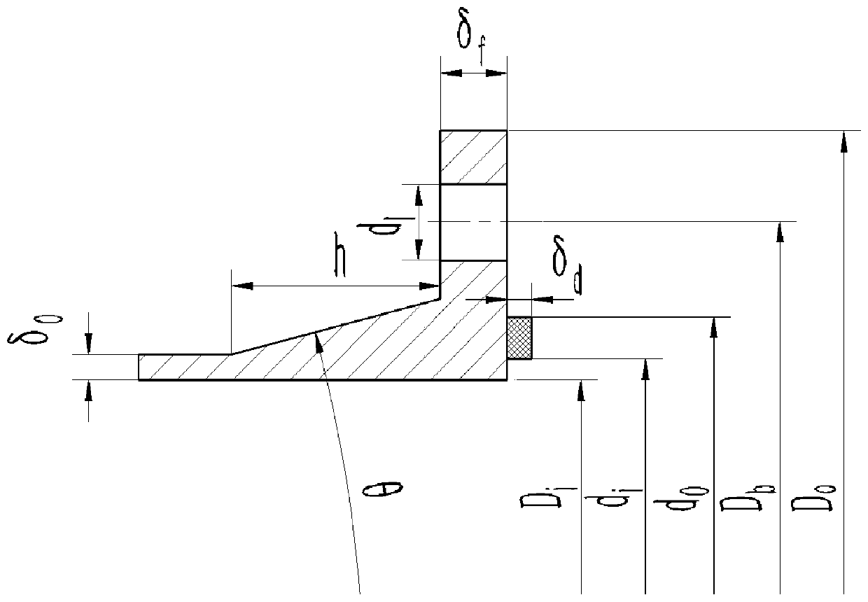
[0110] The wall thickness of the conduit is rounded to 2mm; Δδ is 1mm, and the thickness of the small end of the flange taper neck is δ 0 3mm; flange neck height h is 25mm; flange neck taper angle θ is 30°; ...
specific Embodiment approach 2
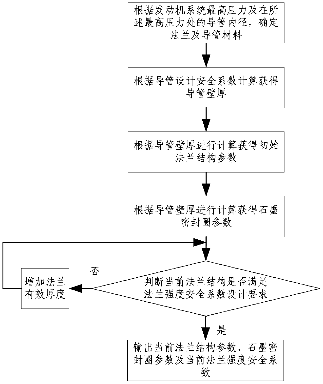
[0136] Embodiment 2. Another aspect of the present invention also provides a rapid design method for a rocket engine flange based on a visual interface, combining image 3 As shown, the method obtains a visual interface based on VB programming, including:
[0137] Using the material selection module, the step of determining the material of the flange and the conduit according to the maximum pressure of the engine system and the internal diameter of the conduit at said maximum pressure;
[0138] Using the conduit wall thickness calculation module to calculate and obtain the conduit wall thickness according to the conduit design safety factor;
[0139] using the flange structure parameter calculation module to calculate the initial flange structure parameters according to the conduit wall thickness;
[0140] Using the graphite sealing ring parameter calculation module to calculate and obtain the parameters of the graphite sealing ring according to the wall thickness of the cond...
PUM
 Abstract
Description
Claims
Application Information
 - R&D
- Intellectual Property
- Life Sciences
- Materials
- Tech Scout
- Unparalleled Data Quality
- Higher Quality Content
- 60% Fewer Hallucinations
Browse by: Latest US Patents, China's latest patents, Technical Efficacy Thesaurus, Application Domain, Technology Topic, Popular Technical Reports.
© 2025 PatSnap. All rights reserved.Legal|Privacy policy|Modern Slavery Act Transparency Statement|Sitemap|About US| Contact US: help@patsnap.com


