Heading smoothing technology-based autonomous underwater vehicle path tracking method
An underwater robot, path tracking technology, applied in instruments, adaptive control, control/regulation systems, etc., can solve problems such as low path tracking accuracy
- Summary
- Abstract
- Description
- Claims
- Application Information
AI Technical Summary
Problems solved by technology
Method used
Image
Examples
specific Embodiment approach 1
[0024] Specific implementation mode 1: In this implementation mode, a specific process of an autonomous underwater robot path tracking method based on heading smoothing technology is as follows:
[0025] Step 1. Measure the state measurement value of the AUV at the initial moment, and set the expected path p(σ) of the AUV;
[0026] Step 2, measuring the state measurement value of the current AUV, and obtaining the path tracking error of the AUV according to the state measurement value of the current AUV and the expected path p(σ) of the AUV;
[0027] Path tracking error e p (t) contains the distance between the current position of the AUV and the position of the desired point at the current moment (x(σ(t)), y(σ(t))), the current heading angle and the desired heading angle ψ(σ(t) )) difference;
[0028] Step 3, optimize the difference between the current heading angle obtained in step 2 and the desired heading angle ψ(σ(t)), and obtain the reference heading input to the contr...
specific Embodiment approach 2
[0032] Specific embodiment two: the difference between this embodiment and specific embodiment one is that the state measurement value of the current AUV is measured in the second step, and the path of the AUV is obtained according to the current state measurement value of the AUV and the expected path p(σ) of the AUV Tracking error; the specific process is:
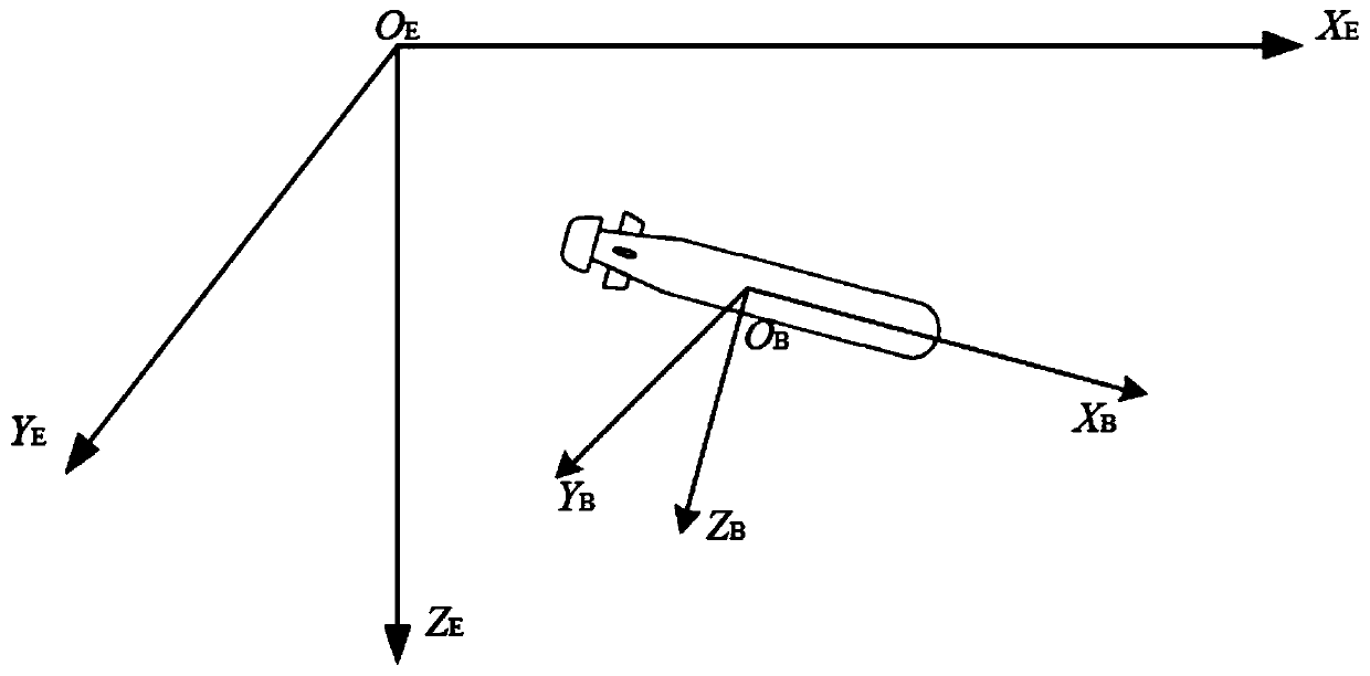
[0033] Set the mathematical model of AUV horizontal plane motion:
[0034]
[0035] where η=[x′ y ψ] T are the coordinates and attitude angle in the geodetic coordinate system, x′, y are the position of the AUV in the geodetic coordinate system, ψ is the heading of the AUV in the geodetic coordinate system, and the superscript T means transpose, is the relationship between the earth coordinate system and the satellite coordinate system, R(ψ) is the horizontal plane coordinate transformation matrix; M=M RB +M A is the inertia matrix; M RB is the rigid body inertial matrix, M A is the additional mass matrix, v=[...
specific Embodiment approach 3
[0058] Specific embodiment three: the difference between this embodiment and specific embodiment one or two is that in the step three, the difference between the current heading angle obtained in step two and the desired heading angle ψ(σ(t)) is optimized , to get the reference heading input to the controller; the specific process is:
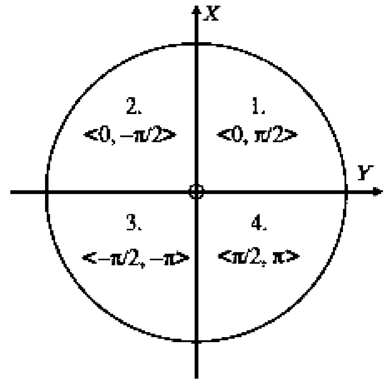
[0059] Because the difference between the current heading and the desired heading angle ψ(σ(t)) has a (-π,π] discontinuity point, causing the AUV to spin, so it is optimized;
[0060] Heading smoothing algorithm:
[0061] Although formula (6) gives the calculation formula of the expected angle of the reference point, the domain of the atan2 function is (-π, π], which will lead to discontinuity at the junction point of -π / π, which is very important for the path tracking problem It is very unfavorable, because it will cause the dynamic inconsistency between the reference heading and the AUV heading. When the AUV is tracking the path, there must ...
PUM
 Abstract
Description
Claims
Application Information
 - R&D
- Intellectual Property
- Life Sciences
- Materials
- Tech Scout
- Unparalleled Data Quality
- Higher Quality Content
- 60% Fewer Hallucinations
Browse by: Latest US Patents, China's latest patents, Technical Efficacy Thesaurus, Application Domain, Technology Topic, Popular Technical Reports.
© 2025 PatSnap. All rights reserved.Legal|Privacy policy|Modern Slavery Act Transparency Statement|Sitemap|About US| Contact US: help@patsnap.com


