
Optical diaphragm module and display device and light-emitting device using same

An optical film and optical technology, applied in the direction of optics, optical components, identification devices, etc., can solve the problems of screen cutting, imperfect image presentation, etc.

Inactive Publication Date: 2019-06-18
胡 崇铭
View PDF18 Cites 0 Cited by
  • Summary
  • Abstract
  • Description
  • Claims
  • Application Information

AI Technical Summary

Problems solved by technology

Similarly, when multiple panels are combined into a single large panel, the frame of individual panels will also cut the picture, resulting in visually imperfect image presentation

Method used


Image

  • Optical diaphragm module and display device and light-emitting device using same
  • Optical diaphragm module and display device and light-emitting device using same
  • Optical diaphragm module and display device and light-emitting device using same

Examples


Embodiment Construction

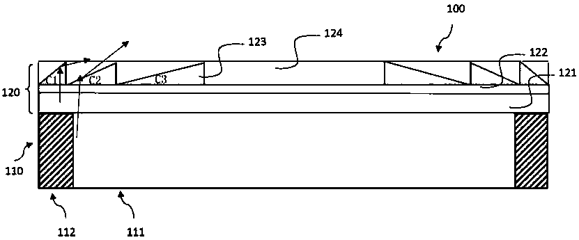
[0104] In order to make the above and other objects, features and advantages of the present invention more comprehensible, preferred embodiments of the present invention will be exemplified below, together with the accompanying drawings, and described in detail as follows. Furthermore, the directional terms mentioned in the present invention are, for example, up, down, top, bottom, front, back, left, right, inside, outside, side, surrounding, outer edge, center, horizontal, transverse, vertical, longitudinal, The axial direction, the radial direction, the uppermost layer or the lowermost layer, etc. are only directions referring to the attached drawings. Therefore, the directional terms used are used to illustrate and understand the present invention, but not to limit the present invention.

[0105] The drawings and descriptions are to be regarded as illustrative in nature and not restrictive. In the figures, structurally similar units are denoted by the same reference numera...


PUM


Abstract

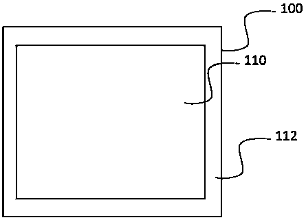
The invention provides an optical diaphragm module and a display device and light-emitting device using the same, wherein the optical diaphragm module is disposed on at least one display unit, and theat least one display unit has an at least dispaly area and an at least one non-display area. The optical diaphragm module comprises an optical euphotic layer disposed on this at least one display unit; micro-lens structures formed on the optical euphotic layer, wherein the micro-lens structures cover on at least a part of the non-display area of the display unit. The optical diaphragm module canbe disposed on the display device or the light-emitting device to form a seamless or bezelless visual effect. The optical diaphragm module also comprise an optical compensation structure used for compensating the brightness in the vicinity of the non-display area in order to reduce the inconsistent brightness of the display device or the light-emitting device.

Description

technical field [0001] The present invention relates to an optical diaphragm module and its application device, in particular to an optical diaphragm module capable of forming a frameless visual effect when a single machine is displayed, or a seam reduction or elimination effect when multiple machines are arranged side by side. A display device and a light emitting device using an optical film module. Background technique [0002] Nowadays, since any display has a peripheral border when displaying, in order to highlight the appearance design, various display manufacturers strive to reduce the visual seam of the display at any cost. In the large-size billboard market, the development of its display is still limited by cost and technical barriers, making it difficult to break through. Therefore, assembling with panels of existing sizes is one of the possible solutions for manufacturing large panels. [0003] However, when a plurality of liquid crystal panels are used for ass...

Claims


Application Information

Patent Timeline
IPC IPC(8): G02B3/00G09F9/00
Inventor 胡崇铭
Owner 胡 崇铭
Learn More