Steel connection structure and its connection method

A connection structure and connection method technology, applied in the direction of building structure and construction, can solve the problems of difficulty in maintaining horizontal beams and inconvenience, and achieve the effect of compact structure and high reliability

Active Publication Date: 2020-10-02
浙江高盛钢结构有限公司
View PDF12 Cites 0 Cited by
  • Summary
  • Abstract
  • Description
  • Claims
  • Application Information

AI Technical Summary

Problems solved by technology

[0004] The above-mentioned existing technical solutions have the following defects: after the steel structure is installed, it is necessary to ensure that the beams are level. When the ground is uneven, or when the pillars are fixed on the ground and subsidence occurs, the beams are difficult to maintain level; in order to overcome this problem, the existing It is extremely inconvenient for the steel structure to be installed with feet or to keep the beam horizontal by re-cutting and welding

Method used


Image

  • Steel connection structure and its connection method
  • Steel connection structure and its connection method
  • Steel connection structure and its connection method

Examples


Embodiment 1

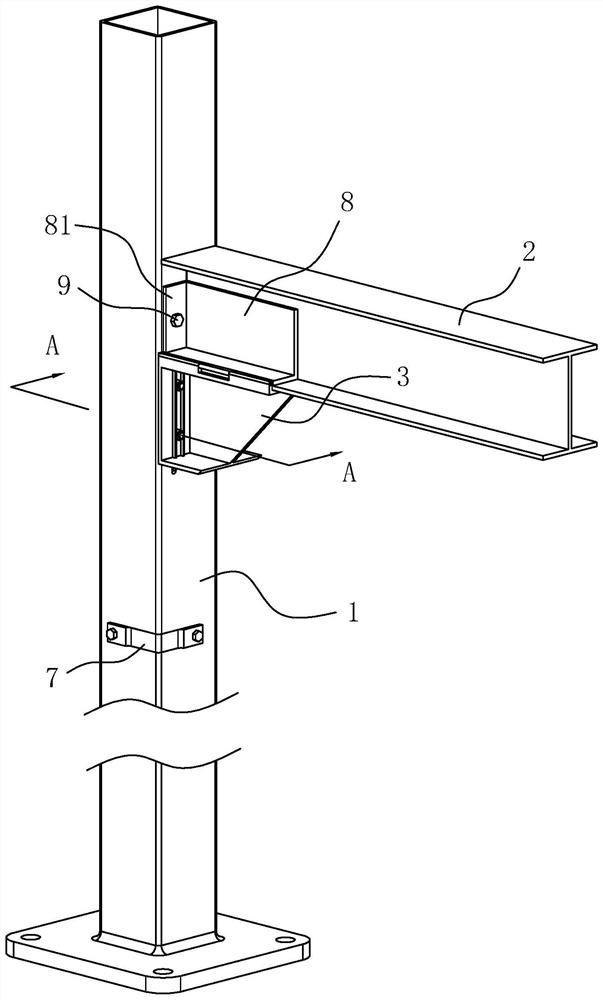
[0043] refer to figure 1 , is a steel connection structure disclosed in the present invention, comprising a pillar 1 and a beam 2, and the pillar 1 is provided with a support 3 for supporting the end of the crossbeam 2; after the installation of the steel connection structure is completed, the pillar 1 passes through the bottom Fixed on the ground, the length direction of the pillar 1 is along the vertical direction, and the length direction of the beam 2 is along the horizontal direction.

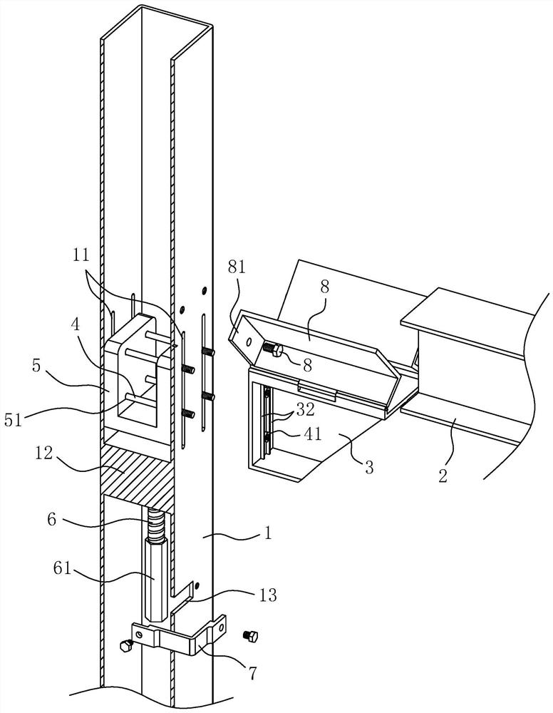
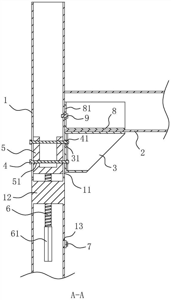
[0044] refer to figure 2 with image 3 , the cross section of the pillar 1 is rectangular, and the interior of the pillar 1 is hollow. The support 3 and the pillar 1 establish a sliding connection through the bolt one 4 passing between the two. Two bolts 4 are arranged along the length direction of the pillar 1 to form a pair, and the bolt one 4 is arranged on the pillar 1 along the horizontal direction. two pairs. The support 3 is provided with a hole for the bolt 1 to pass through, ...

Embodiment 2

[0050] A connection method for connecting the above-mentioned steel connection structure, comprising the following steps:

[0051] Step 1: Install the pillar 1 on the ground, and ensure that the length direction of the pillar 1 is in the vertical direction during installation.

[0052] Step 2: Place the beam 2 on the support 3, and then wait for more than three hours; during the waiting time, the gravity of the beam 2 acts on the pillar 1 through the support 3. If the ground under the pillar 1 subsides, use Settlement is completed on support pillar 1.

[0053] Step 3: Use a spirit level to check the levelness of the beam 2. If the beam 2 is inclined to the horizontal plane, the personnel loosen the bolt 1 4, remove the sealing plate 7, pass the wrench through the operation hole 13 and turn the hexagonal screw head 61, and adjust the support 3 the height until the beam 2 is parallel to the horizontal plane.

[0054] Step 4: Put back the sealing plate 7, and turn the splint 8 ...


PUM


Abstract

The invention discloses a steel part connection structure and a connection method thereof, and relates to the technical field of steel structures. According to key points of the technical scheme, thesteel part connection structure includes a pillar and a cross beam, a support for supporting the cross beam is slidably arranged on the pillar, a first bolt is arranged on the support in a penetratingmode, the pillar is provided with an installation groove allowing the first bolt to penetrate through and slide in the length direction of the pillar, and a sliding seat for supporting the first boltis slidably arranged in the pillar; and the pillar is internally connected with an adjusting rod in a threaded mode, the length direction of the adjusting rod is in the length direction of the pillar, and the adjusting rod abuts against the bottom surface of the sliding seat through the end. The steel part connection structure can conveniently adjust the levelness of the cross beam, the support can move while bearing the weight of the cross beam, the reliability of support movement is high, and the structure of the steel part connection structure is compact, and the overall appearance is notprone to being affected.

Description

technical field [0001] The invention relates to the technical field of steel structures, in particular to a steel connection structure and a connection method thereof. Background technique [0002] Steel structures are widely used in factory buildings and temporary buildings. Steel structures can be built to form the pillar and beam structures of factory buildings. Compared with brick and tile structures and concrete structures, steel structures have the advantages of low cost, convenient installation, and detachability. [0003] The Chinese utility model patent with the existing authorized announcement number CN207419717U discloses a steel structure node member, including a vertical steel plate, a first interspersed plate and a second intersected plate, the first intersected plate and the second intersected plate are respectively connected to the vertical The steel plate parts are interspersed and connected. Both the first intersecting board and the second intersecting bo...

Claims


Application Information

Patent Timeline
Patent Type & Authority Patents(China)
IPC IPC(8): E04B1/24E04B1/58
Inventor 李之强黎洪赵红运
Owner 浙江高盛钢结构有限公司
Why Eureka
Try Eureka