Mechanical hoisting machine

A technology of mechanical hoisting and pulleys, applied to mechanical equipment, components with teeth, belts/chains/gears, etc., can solve the problems of large-volume material handling and labor, and achieve the effect of improving hoisting and labor saving

Inactive Publication Date: 2019-06-18
张萌
View PDF0 Cites 0 Cited by
  • Summary
  • Abstract
  • Description
  • Claims
  • Application Information

AI Technical Summary

Problems solved by technology

[0002] Interior decoration is a hot topic in life these days. During the decoration process, large-volume materials cannot be transported from corridors or stairwells. The current method is to lift them by means of pulleys, but this method is very laborious.

Method used


Image

  • Mechanical hoisting machine

Examples


Embodiment Construction

[0008] In order to make the object, technical solution and advantages of the present invention clearer, the present invention will be further described in detail below in conjunction with the accompanying drawings and embodiments. It should be understood that the specific embodiments described here are only used to explain the present invention, not to limit the present invention.

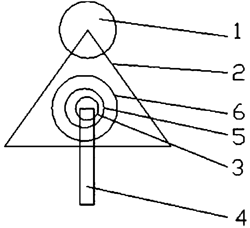
[0009] see figure 1 A mechanical hoisting machine shown includes a pulley 1, which is connected to a tripod 2, and the tripod 2 is provided with a support column 3, and one end is provided with a handle 4, and the handle 4 is connected to a rotating shaft 5, and the rotating shaft 5 is connected to a star wheel 6.

[0010] The star wheel 6 drives the tripod 2 to rotate, and drives the pulley 1 to rotate.

[0011] The working principle of the present invention is: through the rotation of the star wheel, the torque is shortened to achieve the effect of labor saving.

[0012] The above descriptions ...


PUM


Abstract

The invention discloses a mechanical hoisting machine. The mechanical hoisting machine comprises a pulley, wherein the pulley is connected with a tripod, a supporting column is arranged on the tripod,a handle is arranged at one end of the tripod, the handle is connected with a rotating shaft, the rotating shaft is connected with a star wheel, a sterilizing layer is arranged on the handle, the star wheel is rotated, the torque is reduced, and the effect of saving labor is achieved.

Description

technical field [0001] The invention relates to the technical field of building construction, in particular to a mechanical hoisting machine. Background technique [0002] Indoor decoration is a hot topic in life these days. During the decoration process, large-volume materials cannot be transported from corridors or stairwells. The current method is to lift them by means of pulleys, but this method is very laborious. Contents of the invention [0003] The object of the present invention is to provide a mechanical hoisting machine in order to overcome the deficiencies of the prior art. [0004] The present invention is realized through the following technical solutions: [0005] A mechanical hoisting machine, comprising a pulley, the pulley is connected to a tripod, the tripod is provided with a support column, and a handle is provided at one end, the handle is connected to a rotating shaft, the rotating shaft is connected to a star wheel, the handle is provided with a st...

Claims


Application Information

Patent Timeline
IPC IPC(8): B66D3/04
Inventor 张萌
Owner 张萌
Why Eureka
Try Eureka