
Coal mine dredging equipment and coal mine dredging system

A technology for coal mines and equipment, applied in the field of sludge cleaning equipment, can solve the problems of high labor cost, low efficiency, and difficulty in manual dredging, and achieve the effect of compact structure and small space occupation

Pending Publication Date: 2019-06-14
翟文
View PDF13 Cites 0 Cited by
  • Summary
  • Abstract
  • Description
  • Claims
  • Application Information

AI Technical Summary

Problems solved by technology

[0005] The present invention is proposed in view of the above problems, and its purpose is to provide a coal mine dredging equipment and a coal mine dredging system, so as to alleviate the difficulty and low efficiency of manual dredging existing in the prior art, which seriously hinders the normal operation of the coal mining industry. Technical problems with high labor costs

Method used


Image

  • Coal mine dredging equipment and coal mine dredging system
  • Coal mine dredging equipment and coal mine dredging system

Examples


Embodiment 1

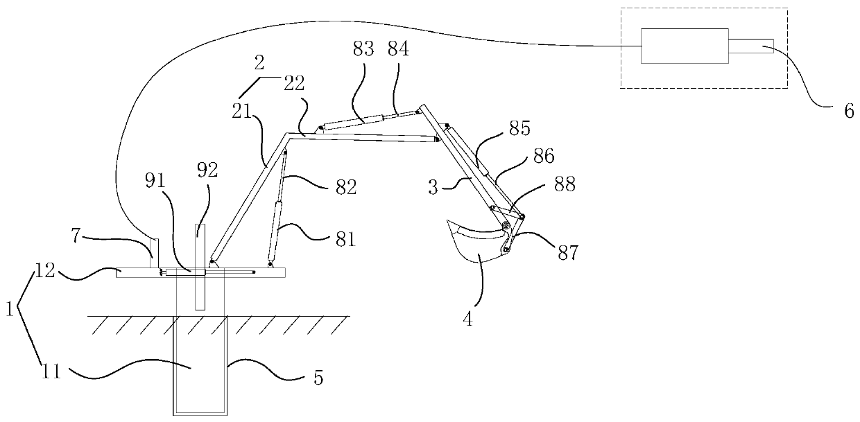
[0040] Please refer to figure 1 , this embodiment provides a coal mine dredging equipment, the coal mine dredging equipment includes a base 1 and working components.

[0041] Specifically, the lower end of the base 1 is fixed in the foundation pit 5; the working assembly includes a first mechanical arm 2, a second mechanical arm 3 and a bucket 4 that are articulated sequentially from approaching to away from the base 1; 1 is connected with a first telescopic device, the first telescopic device can drive the first mechanical arm 2 to rotate around the hinge point hinged with the base 1; between the second mechanical arm 3 and the first mechanical arm 2 is connected a second telescopic device, the second telescopic device can drive the second mechanical arm 3 to rotate around the hinge point hinged with the first mechanical arm 2; a third telescopic device is connected between the bucket 4 and the second mechanical arm 3, and the third telescopic device can Driving the bucket 4...

Embodiment 2

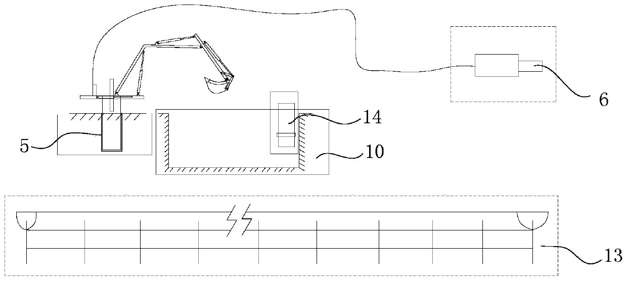
[0058] Please refer to figure 2 , combined with figure 1 , the present embodiment provides a coal mine dredging system, the coal mine dredging system is applied to coal mine roadway, including sedimentation tank 10, foundation pit 5, coal mine conveyor 13, water pump 14 and coal mine dredging equipment; wherein, the sedimentation tank 10 is connected to the flow channel of the coal mine underground roadway; the pump 14 is arranged in the sedimentation tank 10 for pumping out the accumulated water in the sedimentation tank 10; the foundation pit 5 is next to the sedimentation tank 10; the coal mine conveyor 13 is located in the coal mine underground roadway; the coal mine The dredging equipment is configured to be able to shovel out the sludge in the sedimentation tank 10 and transfer it to the coal mine conveyor 13 .

[0059] Wherein, the coal mine dredging equipment includes a base 1 and working components.

[0060] Specifically, the lower end of the base 1 is fixed in the...


PUM


Abstract

The invention provides a coal mine dredging equipment and a coal mine dredging system, and relates to the technical field of sludge cleaning equipment. A base and a working component are included; thelower end of the base is fixed in a foundation pit; the working component comprises a first mechanical arm, a second mechanical arm and a bucket which are sequentially hinged from the part close to the base to the part far away from the base; a first telescopic device capable of driving the first mechanical arm to rotate around a hinge point hinged to the base is connected between the first mechanical arm and the base; a second telescopic device capable of driving the second mechanical arm to rotate around a hinge point hinged to the first mechanical arm is connected between the second mechanical arm and the first mechanical arm; and a third telescopic device capable of driving the bucket to rotate around a hinge point hinged to the second mechanical arm is connected between the bucket and the second mechanical arm. By means of the coal mine dredging equipment and the coal mine dredging system, sludge in a sedimentation tank can be shoveled, and the technical problems that in the prior art, the manual dredging difficulty is large, efficiency is low, normal implementation of the coal mining industry is seriously hindered, and the manual cost is high are alleviated.

Description

technical field [0001] The invention relates to the technical field of sludge cleaning equipment, in particular to coal mine dredging equipment and a coal mine dredging system. Background technique [0002] In the coal mining industry, water and silt will be generated in the underground tunnel of the coal mine due to geological conditions. With the continuous production process, the water and silt will accumulate in large quantities. At this time, the water and silt need to be cleaned. [0003] At present, in industrial production, dredging equipment composed of mud pumps, large excavators, and large loaders is usually used for dredging work. However, for coal mine dredging, due to the narrow space in coal mine underground roadways and The space also needs to accommodate the coal mine conveyor, the excavator and loader in the dredging equipment cannot enter the underground roadway to work, and the accumulated water in the sludge is mixed with the coal mine scum in a highly v...

Claims


Application Information

Patent Timeline
Patent Type & Authority Applications(China)
IPC IPC(8): E02F3/28E02F3/36E02F3/38E21F16/00E21F17/00E21F13/00
Inventor 翟文黄艳利马昆李俊孟董霁红任予鑫
Owner 翟文
Learn More