
A Planar Microstrip Patch Antenna with Broadband Endfire Circular Polarization

A technology of microstrip patch antenna and circular polarization, which is applied in the direction of antenna, antenna grounding switch structure connection, radiation element structure form, etc.

Active Publication Date: 2020-10-20
ARMY ENG UNIV OF PLA
View PDF9 Cites 0 Cited by
  • Summary
  • Abstract
  • Description
  • Claims
  • Application Information

AI Technical Summary

Problems solved by technology

Although different methods can be used to realize the end-fire circularly polarized antenna, it is necessary to ensure the compactness of the structure and realize the broadband characteristics, which puts forward strict requirements on the antenna design, especially to realize the broadband performance of the circularly polarized antenna. It is difficult for antenna engineers to balance the matching bandwidth and ensure that the circular polarization axis ratio bandwidth cannot deviate from the impedance bandwidth.

Method used


Image

  • A Planar Microstrip Patch Antenna with Broadband Endfire Circular Polarization
  • A Planar Microstrip Patch Antenna with Broadband Endfire Circular Polarization
  • A Planar Microstrip Patch Antenna with Broadband Endfire Circular Polarization

Examples


Embodiment approach

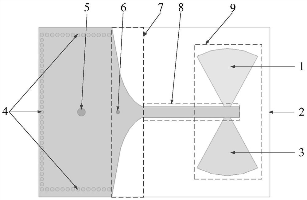
[0035] As a specific implementation, the single-layer dielectric substrate 2 has a length of 38 mm, a width of 28 mm, and a thickness of 3 mm.

[0036] As a specific embodiment, the rectangular patches in the upper layer metal patch 3 and the lower layer metal patch 1 are 28mm long and 12mm wide.

[0037] As a specific implementation manner, the sector-shaped dipole patch 9 has a radius of 10.5 mm and an opening angle of 57°.

[0038] As a specific implementation, the feed strip 8 is 16 mm long and 1.8 mm wide.

[0039] As a specific implementation, the distance between the loading metal probe 6 and the coaxial feeding probe 5 is 6 mm; the radius of the loading metal probe 6 is 0.3 mm.

[0040] The present invention has the planar microstrip patch antenna with broadband end-fire circular polarization characteristics, and the working process is as follows:

[0041] The energy of the antenna is fed by the coaxial probe 5, and the excited electromagnetic wave uses the bent meta...

Embodiment 1

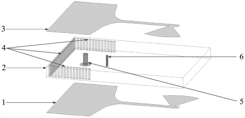
[0044] combine figure 1 , figure 2 , image 3 , the embodiment provides a planar microstrip patch antenna with broadband end-fire circular polarization characteristics at a resonant frequency of 8.25 GHz, including a lower metal patch 1, a single-layer dielectric substrate 2 and an upper layer metal patch 3, wherein The single-layer dielectric substrate 2 includes bent metal walls 4, coaxial feeding probes 5 and loading metal probes 6 arranged from left to right;

[0045] The lower layer metal patch 1 and the upper layer metal patch 3 have the same structure, forming an arc-shaped gradual change slot aperture 7 on the left side, forming a feed strip 8 in the middle, and forming a fan-shaped dipole patch 9 on the right side. The distance between the arc-shaped tapered slot aperture 7 and the fan-shaped dipole patch 9 is about 1 / 4 of the working wavelength, and is connected by a feeding strip 8 .

[0046] Further, the single-layer dielectric substrate 2 is rectangular, with ...


PUM


Abstract

The invention discloses a planar microstrip patch antenna with broadband end-fire circular polarization characteristics. The antenna comprises a single-layer dielectric substrate, an upper metal patchand a lower metal patch, wherein the single-layer dielectric substrate comprises a bent metal wall, a coaxial feed probe and a loading metal probe which are arranged sequentially; the coaxial feed probe is used to feed the energy of the antenna; the bent metal wall is used as a reflection cavity; the loading metal probe is used for adjusting the impedance matching performance of the antenna; theupper metal patch and the lower metal patch sequentially comprise rectangular patches, arc-shaped gradient slot apertures, feed strips and fan-shaped dipole patches from one side to the other side; the arc-shaped gradient slot aperture is used for exciting a vertical polarization component; the feed strip is used for transferring the energy to the fan-shaped dipole patch; and a horizontal polarization component is excited by the fan-shaped dipole patch. The broadband circular polarization radiation function of the planar microstrip patch antenna is realized, and the planar microstrip patch antenna has the advantages of simple structure and wide common bandwidth of impedance and axial ratio.

Description

technical field [0001] The invention relates to the technical field of microstrip antennas, in particular to a planar microstrip patch antenna with broadband end-fire circular polarization characteristics. Background technique [0002] Circularly polarized antennas have the advantages of anti-multipath reflection and suppressing the depolarization of rain and fog, so they are widely used in communication systems such as radar, guidance, and television broadcasting. Circularly polarized antennas are used in satellite navigation and positioning systems including the US GPS global positioning system and the Beidou navigation system independently developed by China. In order to obtain circularly polarized beams, general circularly polarized antennas use complex non-planar structures, or add feed networks such as power dividers, which have side-firing radiation characteristics. However, in practical applications such as aircraft and radio frequency identification systems (RFID),...

Claims


Application Information

Patent Timeline
Patent Type & Authority Patents(China)
IPC IPC(8): H01Q1/38H01Q1/50H01Q13/08
Inventor 曹文权黄荣港马文宇晋军刘涵赵妍卉薛红杨晓琴
Owner ARMY ENG UNIV OF PLA
Learn More