
Paper feeding device for a vertical printing machine

A paper feeding technology for printing machines, which is applied in the directions of transportation and packaging, thin material handling, and object separation, etc. It can solve the problems of damp printing paper, reducing the friction force of the paper pickup roller and friction plate, and the printer cannot be fed normally.

Active Publication Date: 2021-01-26
浙江鸿胜机械有限公司
View PDF11 Cites 0 Cited by
  • Summary
  • Abstract
  • Description
  • Claims
  • Application Information

AI Technical Summary

Problems solved by technology

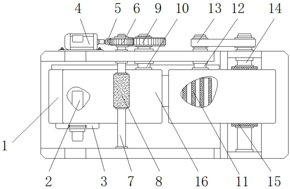
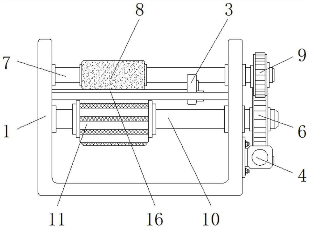
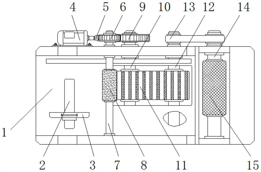
[0005] The invention provides a paper feeding device for a vertical printing machine, which has the advantages of effectively separating printing paper, preventing the printer from feeding multiple sheets at a time, and preventing the printer from feeding paper due to too small frictional force. It solves the problem that when the environment is relatively humid, the printing paper will be damp and sticky, which will cause the printer to feed two or more sheets at a time, and eventually cause the printer to fail to eat normally and shut down. When the environment is relatively dry, the printing paper will Static electricity will be generated between them and they will be attracted to each other. It is difficult to separate them using the existing pickup rollers and friction sheets. There will also be a problem that the printer feeds multiple sheets at a time, and the dry paper will reduce its contact with the pickup roller. The friction between the roller and the friction plate, which causes the problem that the pickup roller is idling and does not feed the paper

Method used


Image

  • Paper feeding device for a vertical printing machine
  • Paper feeding device for a vertical printing machine
  • Paper feeding device for a vertical printing machine

Examples


Embodiment Construction

[0021] The following will clearly and completely describe the technical solutions in the embodiments of the present invention with reference to the accompanying drawings in the embodiments of the present invention. Obviously, the described embodiments are only some, not all, embodiments of the present invention. Based on the embodiments of the present invention, all other embodiments obtained by persons of ordinary skill in the art without making creative efforts belong to the protection scope of the present invention.

[0022] see Figure 1-4 , a paper feeding device for a vertical printing machine, comprising a frame 1, a limit slot 2 is provided on one side of the front of the frame 1, and a clamping plate 3 is movably connected to the inside of the limit slot 2, and one side of the top of the frame 1 The drive motor 4 is threadedly connected, the output shaft of the drive motor 4 is fixedly equipped with a transmission screw 5, the outer surface of the transmission screw 5...


PUM


Abstract

The invention relates to the technical field of intelligent manufacturing, and discloses a paper feeding device for a vertical printing machine, which includes a frame, a limiting slot is provided on one side of the front of the frame, and a clamping plate is movably connected to the inside of the limiting slot, and the frame One side of the top end is threadedly connected with a driving motor, and the outer surface of the transmission screw rod is provided with a transmission gear. The paper feeding device for the vertical printing machine, through the setting of the transmission gear, the paper pickup roller, the driven gear and the friction belt, drives the paper pickup roller and the friction belt to rotate synchronously and reversely. When the paper feeding device is working, the printing paper There will be a speed difference between the upper and lower sides of the upper and lower sides, so as to effectively separate the overlapping printing paper. Compared with the existing technology, the speed difference is used to separate the sticky and adsorbed printing paper, which has high efficiency and stability. Good performance and strong paper pickup force, it will not appear that the friction between the printing papers cannot be separated due to excessive friction, or the situation that the paper pickup roller is idling and does not feed paper due to too small friction.

Description

technical field [0001] The invention relates to the technical field of intelligent manufacturing, in particular to a paper feeding device for a vertical printing machine. Background technique [0002] The paper feeding device of the printer is a device that feeds unprinted paper into the printer for printing, and since the printer prints one by one, the paper feeding device must ensure that the printed paper fed into the printer is There is only one piece of paper. [0003] Therefore, in order to ensure that there is one and only one piece of paper entering the printer, the currently used paper feeding devices use the different friction forces between the pickup roller, printing paper and friction plates to separate and feed the paper, so that Avoid the problem that two or more sheets of printing paper enter the printer at the same time, but because the friction between the printing papers is not constant, when the environment is relatively humid, the printing paper will be...

Claims


Application Information

Patent Timeline
Patent Type & Authority Patents(China)
IPC IPC(8): B65H3/46B65H3/06
Inventor 不公告发明人
Owner 浙江鸿胜机械有限公司
Learn More