
Hydraulic switch machine for urban rail

A technology of urban rail and switch machines, applied in the field of rail transit, can solve the problems of large switch machines, easy to be affected by damp or water, high manufacturing precision requirements of two-way oil pumps, etc., so as to improve operation reliability and safety, prolong Service life and reliability, internal structure optimization and practical effects

Active Publication Date: 2019-06-07
CRSC RESEARCH & DESIGN INSTITUTE GROUP CO LTD
View PDF7 Cites 5 Cited by
  • Summary
  • Abstract
  • Description
  • Claims
  • Application Information

AI Technical Summary

Problems solved by technology

At present, most of the switch machines used in urban rail tram systems in China are large in size and high in height, and need to reserve deep tunnels, which causes inconvenience to installation and construction; most of the switch machines cannot adapt well Frequent breakouts and automatic recovery of breakouts; most switch machines have low protection levels, and the inside of the machine is prone to moisture or water accumulation, which affects the life and reliability of the switch machines
[0004] In addition, most of the existing railway hydraulic switch machines use two-way pumps to adapt to the two-way conversion of the turnout. Since the oil pump will have certain differences in the two directions after long-term use, such as different displacements, when operating the turnout, the movement in the two directions will be different. There will be a certain difference in time, which will have a certain impact on the consistency of the conversion
In addition, the manufacturing precision of the bidirectional oil pump is relatively high, and the requirements for external electrical control are relatively complicated.

Method used


Image

  • Hydraulic switch machine for urban rail
  • Hydraulic switch machine for urban rail
  • Hydraulic switch machine for urban rail

Examples


Embodiment Construction

[0038] In order to make the purpose, technical solutions and advantages of the embodiments of the present invention more clear, the technical solutions in the embodiments of the present invention will be clearly and completely described below in conjunction with the accompanying drawings in the embodiments of the present invention. Obviously, the described embodiments It is a part of embodiments of the present invention, but not all embodiments. Based on the embodiments of the present invention, all other embodiments obtained by persons of ordinary skill in the art without making creative efforts belong to the protection scope of the present invention.

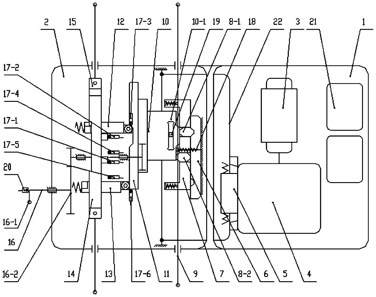
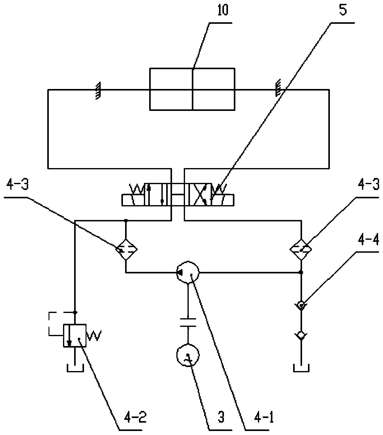
[0039] figure 1It is a structural schematic diagram of the switch machine of the present invention. The device is composed of an electrical part 1 and a mechanical part 2. Electrical components such as the motor 3 of the switch machine, the pump valve group 4, the electromagnetic reversing valve 5, and the electrical box 21 a...


PUM


Abstract

The invention discloses a hydraulic switch machine for an urban rail. The hydraulic switch machine for the urban rail comprises an electrical part and a mechanical part; the electrical part comprisesa motor, a pump valve group, an electromagnetic reversing valve and an electrical box; and the mechanical part comprises a main locking mechanism, an auxiliary locking mechanism, a manual mechanism and a sensor group. The electrical part and the mechanical part are correspondingly placed in two independent shells; and the two shells are connected with each other through a pipeline. The hydraulic switch machine for the urban rail has the advantages that the structure is optimized, practical, simple and reliable; reversing and conversion of an oil passage are realized through the electromagneticreversing valve; an oil pump rotates in one direction; switch split representation can be realized while main and auxiliary double-locking functions are realized; by using a sensor representation mode, intelligent control is convenient to realize; an electric operation automatic recovering function after switch split of the switch machine is realized; and after frequent switch split, higher working stability can still be kept.

Description

technical field [0001] The invention belongs to the technical field of rail transit, and in particular relates to a hydraulic switch machine for urban rail. Background technique [0002] Urban rail transit is an important public transportation mode in the city. The conversion of its running track is completed by a switch machine. The switch machine is an important railway switch switching equipment. Direction, and supervision and inspection of the position of the turnout. The switch machine is an important guarantee to ensure the safety of railway traffic and improve transportation efficiency. [0003] The track of the urban rail transit above the ground, such as a tram, will occupy the road. In order not to affect the urban road traffic, the switch machine is generally located in a closed space below the road. At present, most of the switch machines used in urban rail tram systems in China are large in size and high in height, and need to reserve deep tunnels, which cause...

Claims


Application Information

Patent Timeline
Patent Type & Authority Applications(China)
IPC IPC(8): B61L5/04
Inventor 孙晓勇许可证刘尚超杨树仁黄天新张玉林王献刘振华
Owner CRSC RESEARCH & DESIGN INSTITUTE GROUP CO LTD
Learn More