
Battery placing and positioning system

A positioning system and battery technology, applied in the field of power stations, can solve the problems of low accuracy and high cost of positioning methods, and achieve the effect of low cost, reduced cost and accurate mobile position

Pending Publication Date: 2019-06-07
SHANGHAI DIANBA NEW ENERGY RESOURCES SCI & TECH +1
View PDF8 Cites 5 Cited by
  • Summary
  • Abstract
  • Description
  • Claims
  • Application Information

AI Technical Summary

Problems solved by technology

[0004] The technical problem to be solved by the present invention is to provide a low-cost and high-accuracy battery placement positioning system in order to overcome the defects of high cost and low accuracy of the positioning method in the prior art

Method used


Image

  • Battery placing and positioning system
  • Battery placing and positioning system
  • Battery placing and positioning system

Examples


Embodiment Construction

[0035] The present invention will be further described by means of embodiments below in conjunction with the accompanying drawings, but the present invention is not limited to the scope of the described embodiments.

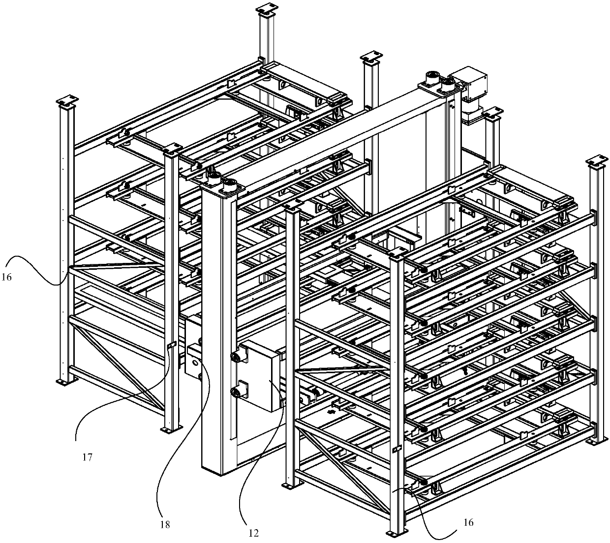
[0036] like figure 1 As shown, the battery positioning system 10 includes: a battery transfer device 11 , a battery rack 16 , a camera 18 , a control unit 19 and a storage unit 20 .

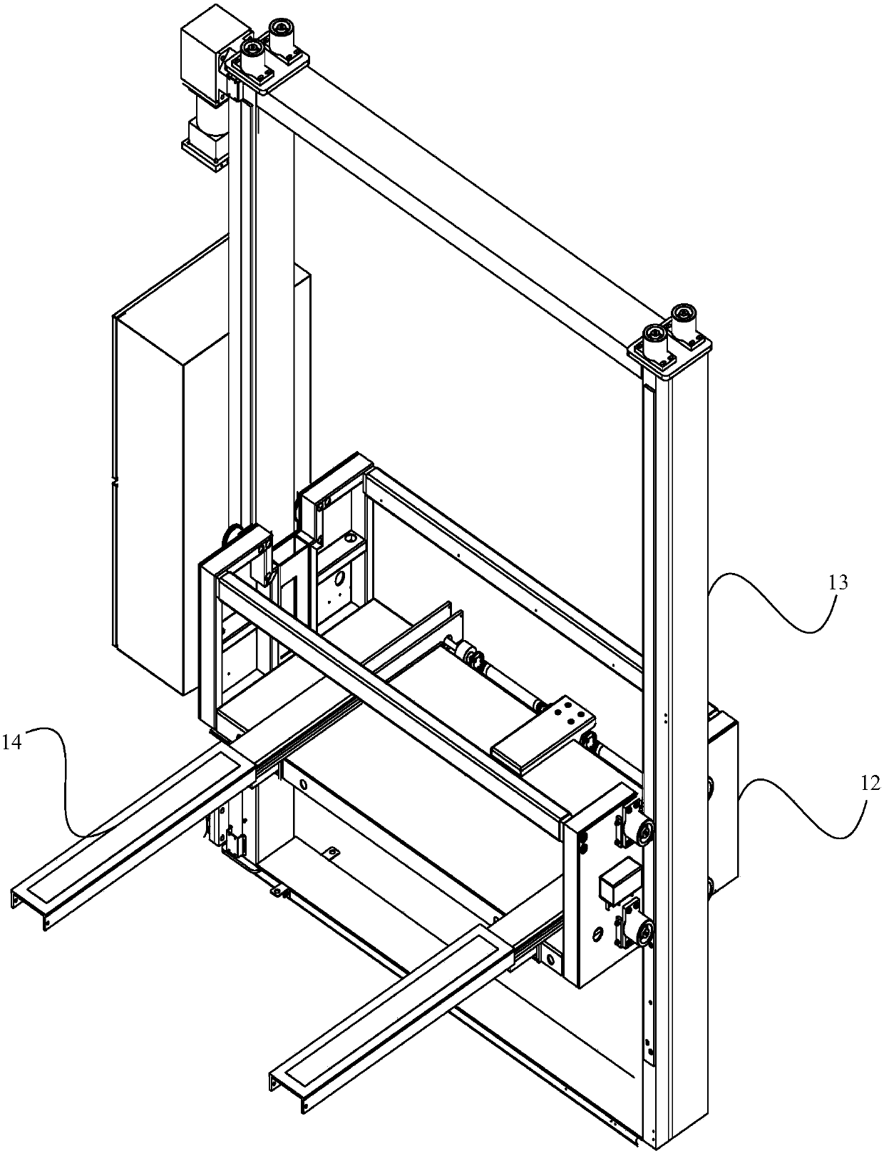
[0037] like Figure 2-3 As shown, the battery transfer device 11 includes: a car 12 , a frame 13 , a telescopic fork 14 and a driving device 15 . The car 12 is arranged in the frame 13 and can move up and down along the frame 13 , the driving device 15 is used to drive the car 12 to move, and the camera 18 is arranged on the side of the car 12 . The telescopic fork 14 is arranged on the car 12 and can extend or retract the car 12 from the car 12 to pick and place the battery.

[0038] The camera 18 is connected to the car 12 through a bracket. In other embodiments, the camera 18...


PUM


Abstract

The invention discloses a battery placing and positioning system which comprises a battery transfer device, a battery rack, a camera and a control unit; the battery transfer device comprises a lift car, a frame and a driving device; the lift car is arranged in the frame and can move up and down along the frame; the driving device is used for driving the lift car to move, and the camera is arrangedon the lift car; a positioning mark is arranged on the surface, facing the battery transfer device, of the battery rack; the control unit is electrically connected with the camera and the driving device and controls operation of the driving device according to images shot by the camera. According to the battery placing and positioning system, whether the lift car moves to an accurate position ornot is judged through pictures shot by the camera, so that the driving device is controlled to move the lift car to the accurate position; the moving position of the lift car is accurate, the cost ofthe camera is lower than that of laser equipment, and the cost of battery replacement equipment is reduced.

Description

technical field [0001] The invention relates to the field of battery swapping stations, in particular to a battery placement and positioning system. Background technique [0002] At present, the emission of vehicle exhaust is still an important factor in environmental pollution. In order to control vehicle exhaust, people have developed natural vehicles, hydrogen fuel vehicles, solar vehicles and electric vehicles to replace fuel vehicles. One of the most promising applications is electric vehicles. Current electric vehicles mainly include two types: direct charge type and quick change type. [0003] Quick-change electric vehicles generally perform battery replacement in a battery replacement station. After the battery is removed from the electric vehicle, it needs to be placed on the corresponding battery rack through the battery transfer device for charging. At this time, the battery transfer device needs to be positioned to accurately deliver the battery to the selected...

Claims


Application Information

Patent Timeline
IPC IPC(8): B60S5/06
Inventor 黄春华陈志浩黄维春
Owner SHANGHAI DIANBA NEW ENERGY RESOURCES SCI & TECH
Learn More