Warp knitting machine with jacquard device and for lace
A lace and warp knitting machine technology, applied in the warp knitting machine field, can solve the problems of inconvenient use, poor environmental performance, and low work efficiency, and achieve the effects of convenient conversion, good sealing performance, and good effect
- Summary
- Abstract
- Description
- Claims
- Application Information
AI Technical Summary
Problems solved by technology
Method used
Image
Examples
Embodiment 1
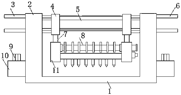
[0027] see Figure 1-8 As shown, a warp knitting machine for lace with a jacquard device includes a base plate 1, a side plate 2, a fixed rod 5, a rotating shaft 8 and a jacquard head 18, and the side plates 2 are welded on both sides of the top of the base plate 1 , and one side of the side plate 2 is connected to a hydraulic oil tank 10, and an oil pump 9 is installed inside the hydraulic oil tank 10 to ensure that the two hydraulic columns can work normally during work. The hydraulic column has a power source, and the work is more stable and safe. Two sets of first hydraulic columns 3 and two sets of second hydraulic columns 6 are respectively connected to one side of the plate 2, which can push the collar 4 to move on the fixed rod 5 during work, and then drive the jacquard head 18 to reciprocate horizontally during work. The work of two side plates 2 tops is connected with a fixed rod 5, and the outer two ends of the fixed rod 5 are equipped with collars 4, and four sets ...
Embodiment 2
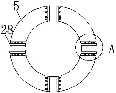
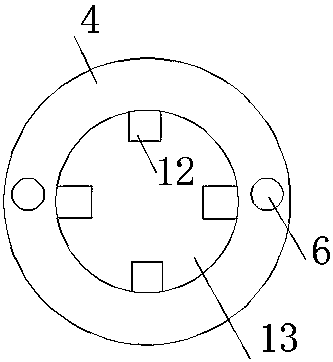
[0029] Additionally, according to Figure 1-4 As shown, the difference between it and the above-mentioned embodiment is that: the inside of the collar 4 is provided with a perforation 13, and the inside of the perforation 13 is evenly connected with four sets of protrusions 12, so that the collar 4 can be stably set on the fixed rod 5, and the working It is not easy to slip, and the stability performance is improved. Bearings 15 are provided at the connection between the two ends of the rotating shaft 8 and the mounting plate 11, and the rotating shaft 15 and the box body 19 are arranged in a flat shape, so that the rotating shaft 8 can rotate stably between the two mounting plates 11 without affecting the installation. In normal use of the plate 11, the cam 14 on the rotating shaft 8 can be in uniform contact with the pressing plate 20 at the bottom. Both sides of the sliding groove 28 are connected with clamping plates 27, and several vertically arranged coil springs 26 are...
PUM
 Abstract
Description
Claims
Application Information
 - R&D
- Intellectual Property
- Life Sciences
- Materials
- Tech Scout
- Unparalleled Data Quality
- Higher Quality Content
- 60% Fewer Hallucinations
Browse by: Latest US Patents, China's latest patents, Technical Efficacy Thesaurus, Application Domain, Technology Topic, Popular Technical Reports.
© 2025 PatSnap. All rights reserved.Legal|Privacy policy|Modern Slavery Act Transparency Statement|Sitemap|About US| Contact US: help@patsnap.com


