
Magnetic latching relay

A technology of magnetic latching relays and magnetic steel, applied in electromagnetic relays, relays, non-polar relays, etc., can solve problems such as increased coil power, smaller coil space, and increased difficulty in production processes

Pending Publication Date: 2019-05-31
苏州吉控电器有限公司
View PDF1 Cites 0 Cited by
  • Summary
  • Abstract
  • Description
  • Claims
  • Application Information

AI Technical Summary

Problems solved by technology

[0003] With the need for energy saving and environmental protection, the application range of magnetic latching relays is becoming wider and wider. More and more general-purpose relays need to expand the magnetic latching specifications. To achieve magnetic latching in typical snap-in relays, generally the iron core (or yoke Iron) is divided into two parts, and a permanent magnet is connected in series to form a series magnetic circuit. When the coil is excited, the magnetic circuit is closed, and the magnetic force generated by the permanent magnet can keep the armature closed; the existing clapping magnetic circuit system The current magnetic retention technology is to install the magnetic steel on the yoke (there are two ways of yoke integration and yoke split riveting), such as the Chinese patent document with the announcement number: CN103426690B, which discloses a parallel magnetic circuit The disadvantage of the magnetic latching relay is that due to the influence of the yoke iron and the magnetic steel, the space left for the coil becomes smaller, resulting in a larger coil power; in addition, because the yoke iron needs to be integrally riveted with the coil and the iron core before it can be loaded into the relay The existence of the base, magnetic steel and auxiliary yoke increases the difficulty of the production process, which is not conducive to the implementation of automation

Method used


Image

  • Magnetic latching relay
  • Magnetic latching relay
  • Magnetic latching relay

Examples


Embodiment

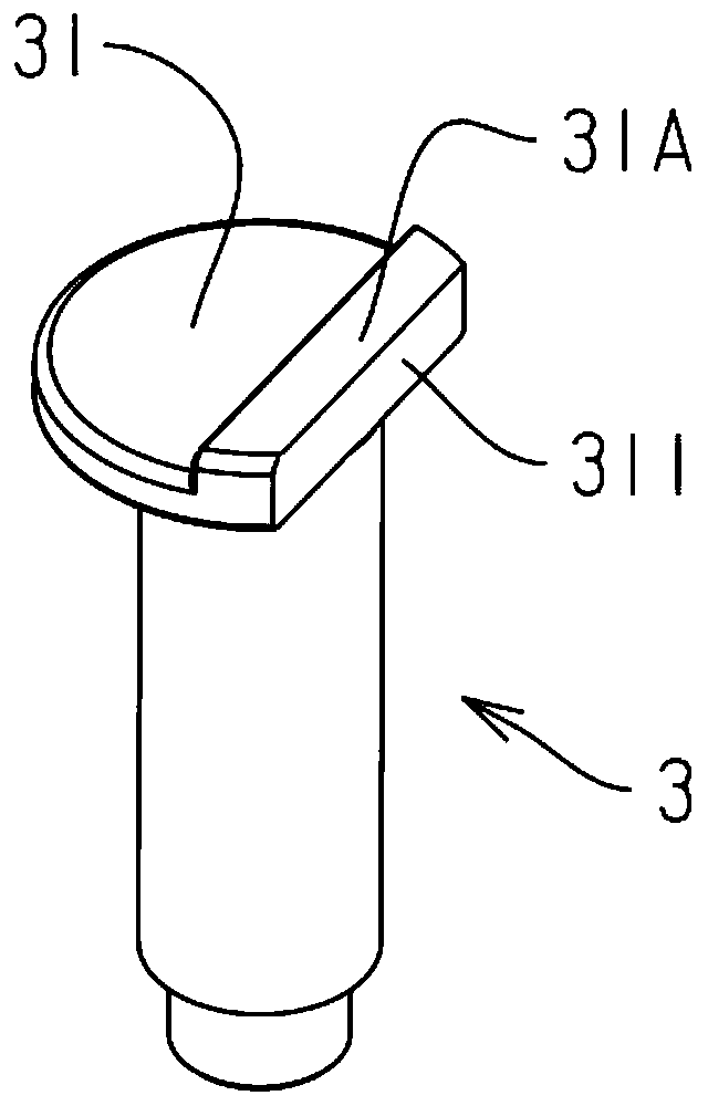
[0031] Embodiment: a kind of magnetic latching relay, such as figure 1 Shown: includes a yoke 1, an armature 2 and an iron core 3, the armature and the yoke are elastically connected through a reed 4, the iron core is wound with a coil (not shown in the figure), the iron core The suction end has a pole piece 31, such as figure 2 and image 3 As shown: the upper surface of the pole shoe has a protrusion 31A or a groove 31B, and the height difference between the iron core and the armature is adjusted by the height difference between the protrusion or the groove and the upper surface of the pole shoe. The gap between the magnetic circuits, so as to achieve the balance of the attractive force of the magnetic circuit on the armature and the reset force (actually adjust the set voltage and reset voltage).

[0032] There is a cutout 311 on one side of the pole shoe, through which the attraction force of the iron core to the armature is adjusted before and after attraction;

[003...


PUM


Abstract

The invention discloses a magnetic latching relay comprising a yoke, an armature and an iron core, wherein the armature and the yoke are elastically connected by a reed; a coil is wound around the iron core; the suction end of the iron core is provided with a pole shoe; the upper surface of the pole shoe has a projection or a groove; the armature is provided with magnetic steel; and the position of the magnetic steel corresponds to the position of the iron core. A magnetic circuit gap between the iron core and the armature is adjusted by a height difference between the protrusion or the grooveand the upper surface of the pole shoe, thereby realizing the balance of the armature under the effect the attraction force and the reset force of the magnetic circuit. The armature is provided withthe magnetic steel. When the armature is closed, the magnetic circuit of the magnetic steel is closed, thereby achieving the actuation latching of the armature.

Description

technical field [0001] The invention belongs to the technical field of relays, in particular to a magnetic latching relay. Background technique [0002] The relay is an electronic control device, which plays the role of automatic adjustment, safety protection, conversion circuit, etc. in the circuit. Its working principle is that a certain voltage is applied to both ends of the coil, and a certain current will flow through the coil, thereby An electromagnetic effect is generated on the magnetic circuit, and the armature will overcome the pulling force of the return spring and attract to the iron core under the action of electromagnetic force, thereby driving the moving contact on the moving spring to attract the static contact on the static spring to achieve conduction in [0003] With the need for energy saving and environmental protection, the application range of magnetic latching relays is becoming wider and wider. More and more general-purpose relays need to expand the...

Claims


Application Information

Patent Timeline
IPC IPC(8): H01H51/01H01H50/16H01H50/36H01H50/18
Inventor 王彬
Owner 苏州吉控电器有限公司
Learn More