
Special coding machine for cables

A special coding and cable technology, used in typewriters, printing devices, printing and other directions, can solve the problems of high cable layout requirements, many coding technologies, and failure to realize special application of cable coding.

Pending Publication Date: 2019-05-31
STATE GRID SHANDONG ELECTRIC POWER CO SHOUGUANG POWER SUPPLY CO +1
View PDF0 Cites 0 Cited by
  • Summary
  • Abstract
  • Description
  • Claims
  • Application Information

AI Technical Summary

Problems solved by technology

[0004] 1. At present, the cable site uses a lot of labor to fix and hang the cable tags at both ends after the construction is completed. At the same time, due to the construction period, human factors and other reasons, it is very easy to cause the inconsistency between the hung cable tags and the marked cables. Limited to the experience of the construction personnel, it will bring great difficulties to the follow-up maintenance and construction personnel to accurately identify the serial number of the corresponding cable
[0005] 2. With the construction and development of urban power grids, the outgoing lines of substations are all outgoing lines of cables, resulting in high requirements for cable layout in cable trenches and construction tunnels. However, in the process of cable transformation and maintenance, the established cable correspondence can only rely on cable pipelines Drawing confirmation requires a lot of manpower and material resources to confirm the cable name and corresponding relationship. Some directly buried multi-channel cables outside the station cannot be accurately confirmed when they are faulty or replaced, which brings great safety hazards to the emergency repair of the power grid and the safety of construction personnel.
[0006] 3. The ex-factory coding technology of cables is mostly used in the factory, and is suitable for the factory production line coding of cables. The coding content of the construction site is different due to the different sites. Although there are many coding technologies used in other fields , but failed to realize the special application of cable coding

Method used


Image

  • Special coding machine for cables
  • Special coding machine for cables
  • Special coding machine for cables

Examples


Embodiment Construction

[0025] The present invention will be further explained below in conjunction with the drawings and embodiments. In the following detailed description, only certain exemplary embodiments of the present invention are described by way of illustration. Needless to say, those of ordinary skill in the art can realize that the described embodiments can be modified in various ways without departing from the spirit and scope of the present invention. Therefore, the drawings and description are illustrative in nature, and are not used to limit the protection scope of the claims.

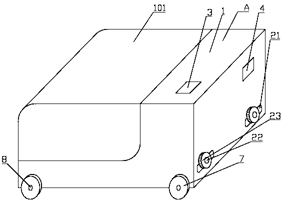
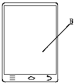
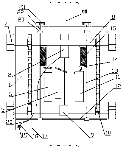
[0026] With reference to the drawings, the cable dedicated encoder includes a movable encoding mobile box A and a handheld terminal B for controlling the encoding mobile box A. The handheld terminal B is used to send various instructions to the encoding mobile box A and view the encoding The real-time image returned by the image positioning device in the moving box A realizes precise control of the spraying of th...


PUM


Abstract

The invention discloses a special coding machine for cables. The special coding machine for the cables comprises a movable coding moving box and a handheld terminal used for controlling the coding moving box; the coding moving box comprises a box body with an opened bottom; a top plate of the box body is provided with a top cover capable of being opened; and the box body is internally provided with a control module, a drive transmission device, an image positioning device and a code spraying device. By adopting the special coding machine for the cables, flexible receiving and releasing of thecoding moving box are realized, and manual flexible code spraying is realized as for space and position limited places; and the coding moving box adopts remote control intelligent control, timely reports obstacle types when encountering various obstacles in the construction site and can timely change a position to cross the coding obstacles for next dynamic coding as before, so that flexible adaptation to the construction site is realized, and the space limitation of cable coding is broken.

Description

Technical field [0001] The invention relates to a cable marking coding technology, in particular to a cable dedicated coding machine. Background technique [0002] At present, there are a large number of cables in substations, which are distributed in cable trenches, and multiple cables are mixed in the same space. Nowadays, most of them are distinguished by means of cable plates. Affected by space and location, it is easy to cause confusion in cable identification. One-step overhaul and troubleshooting, especially transformation, bring greater difficulty, and at the same time, it is greatly affected by personnel adjustment and business level, which brings security risks to the safe operation of the power grid. Through the research on the construction characteristics, layout and operation mode of the cables, the cable coding machine is specially studied to realize the standard numbering of the cables on the construction site, realize the seamless identification of the cables, and...

Claims


Application Information

Patent Timeline
IPC IPC(8): B41J2/01B41J3/01B41J11/00B41J29/393
Inventor 张金峰张柄楠张玉磊田兴华李宝国韩新华刘本忠李晓明窦鹏李文杰周群林李兆东吕会岗张建国周思玉毕红强陈明
Owner STATE GRID SHANDONG ELECTRIC POWER CO SHOUGUANG POWER SUPPLY CO
Learn More