
Eight sided forged ferrule staking crimped fitting and method of manufacture thereof

A technology for ferrules and fittings, applied in the direction of sealing surface connection, pipe/pipe joint/pipe fitting, through components, etc., which can solve the problems of leakage at brazing joints and increased cost.

Active Publication Date: 2019-05-28
CONTITECH USA INC
View PDF5 Cites 0 Cited by
  • Summary
  • Abstract
  • Description
  • Claims
  • Application Information

AI Technical Summary

Problems solved by technology

[0006] Brazing the two rod sections together requires an additional process step, which adds cost and creates potential leaks at the brazed connection

Method used


Image

  • Eight sided forged ferrule staking crimped fitting and method of manufacture thereof
  • Eight sided forged ferrule staking crimped fitting and method of manufacture thereof
  • Eight sided forged ferrule staking crimped fitting and method of manufacture thereof

Examples


Embodiment Construction

[0018] The following description of variants is merely illustrative in nature and is in no way intended to limit the scope, application or use of the disclosure. The description presented herein is only for the purpose of illustrating various embodiments of the disclosure and should not be construed as limiting the scope and applicability of the disclosure. In the Summary of the Disclosure and this Detailed Description, each numerical value should be read once as modified by the term "about" (unless it has expressly been so modified), and then again as if not so modified Read unless the context indicates otherwise. Furthermore, in the Summary of the Disclosure and this Detailed Description, it is to be understood that ranges of values ​​listed or described as useful, suitable, etc., are intended to be that all values ​​within the range, including endpoints, are considered to have been stated . For example, "range from 1 to 10" will be read to indicate every possible number a...


PUM


Abstract

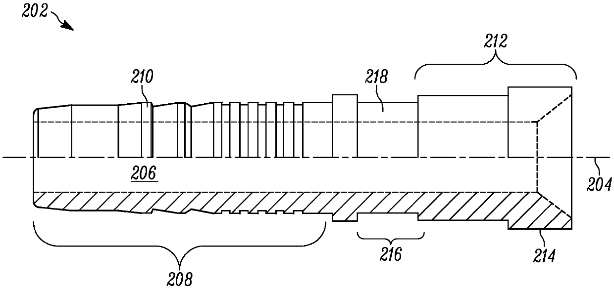
Methods of making hose fittings include providing a stem having a fluid conduit, a first end, a second end with a raised shoulder, and a crimp region disposed between the first end and the second end.A swivel tube nut is placed over the stem, and the swivel tube nut is retained on the stem by the raised shoulder. A ferrule is thereafter placed over the first end of the stem, and the ferrule comprises a partially or fully formed octagonal wrench surface, formed prior to. The ferrule is then crimped, at the octagonal wrench surface, onto the crimp region of the stem.

Description

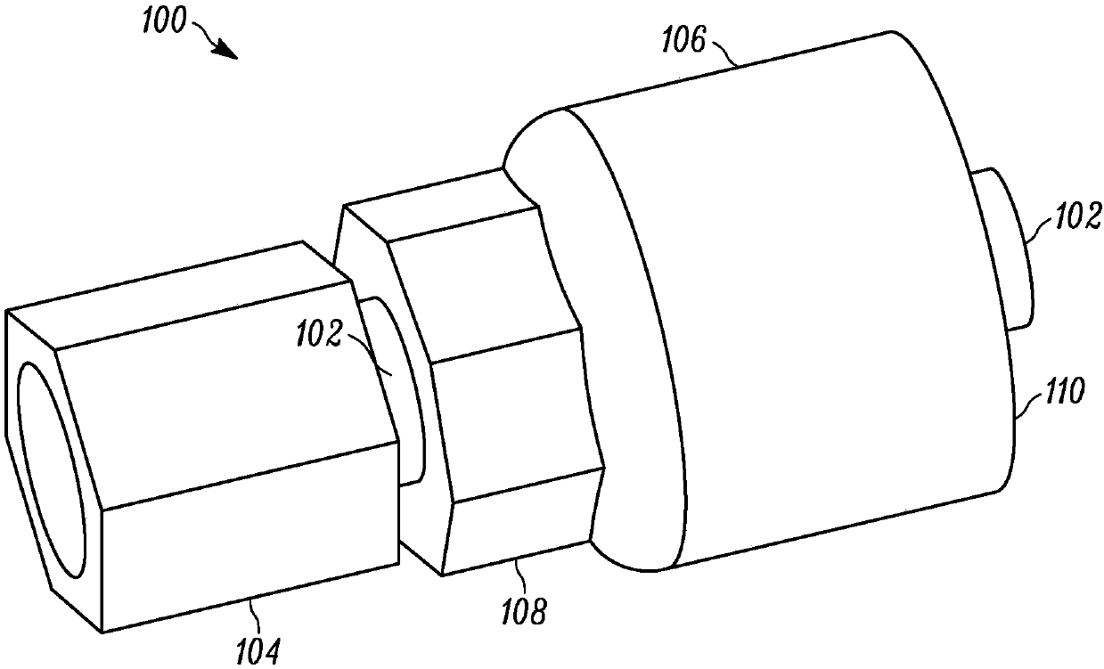
technical field [0001] The present disclosure relates generally to hydraulic hose fittings, and methods of making such fittings, and more particularly to octagonal shapes on the exterior of the ferrule of the fitting. Background technique [0002] This section provides background information to facilitate a better understanding of various aspects of the disclosure. It should be understood that the statements in this section of this document are to be read in this light and are not admissions as prior art. [0003] Use hose fittings to connect fluid lines or hoses to various types of industrial equipment and machinery via equipment connection ports or manifolds. Hose fittings generally have two ends: one end generally defines a hose connection end, and the other end generally defines an equipment connection end. In one type of hose fitting, a rod is provided having a first end (equipment connection end) and a second end (hose connection end), wherein the second end includes...

Claims


Application Information

Patent Timeline
Patent Type & Authority Applications(China)
IPC IPC(8): F16L33/22
CPCF16L33/2076F16L33/22B21D39/048F16L19/025F16L33/30
Inventor 克雷格·博赫杰里米·杰伊·里吉特
Owner CONTITECH USA INC
Learn More