Networked displacement recirculation ventilation cluster system

A cluster system and recirculation technology, applied in space heating and ventilation, space heating and ventilation details, heating methods, etc., can solve the waste and consumption of heating energy, and can not solve the lifting of dust pollutants in the work area and ventilation and other issues, to achieve the effect of reasonable layout, sealing and energy saving

Active Publication Date: 2021-04-16
MEGAUNITY ENVIRONMENTAL SOLUTIONS CO LTD
View PDF6 Cites 0 Cited by
  • Summary
  • Abstract
  • Description
  • Claims
  • Application Information

AI Technical Summary

Problems solved by technology

[0004] Disadvantage: When the emission of pollutants is high, the air change rate cannot be met
[0006] Disadvantages: The accumulation height of exhaled dust aerosol is usually below 6.5m, and the roof ventilation of buildings above 8m cannot solve the lifting and ventilation of exhaled dust pollutants in the work area. For the northern heating area in winter, it also causes a lot of waste of heating energy, and the heating effect cannot be guaranteed , so it cannot be used in winter
[0008] Disadvantages: The huge exhaust system collects and filters the polluted air in each work area, and then sends it to the work area evenly through the huge air supply system. 75% of the fan energy is used to transport the air flow back and forth, resulting in a large amount of energy Consumption, and because the layout of the air duct system is restricted by the structure, there are many blind areas of exhaust and air supply, that is, uncontrollable pollution areas
In addition, centralized control in a large area is more costly for small-scale production or overtime ventilation.

Method used


Image

  • Networked displacement recirculation ventilation cluster system
  • Networked displacement recirculation ventilation cluster system
  • Networked displacement recirculation ventilation cluster system

Examples


Embodiment Construction

[0045] Below in conjunction with specific implementation methods and attached Figure 1-18 The present invention is described further:

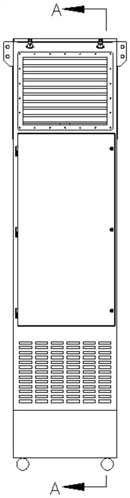
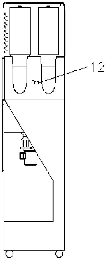
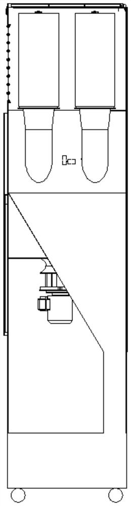
[0046]In the networked displacement recirculation ventilation cluster system, several displacement filter ventilation units 16 connected in series or in parallel or mutually independent are installed in the factory building. When the temperature in the factory building exceeds the threshold value or the dust concentration increases to the threshold value, the replacement filter ventilation unit 16 receives the start command from the control center to start it, and the control center communicates with the mobile phone through the network. The mobile phone APP that sends an activation command to the control center, after the activation command is sent, the control center receives and controls the activation of the replacement filter ventilation unit 16 for temperature regulation or dust removal. The temperature is detected by the temperature s...


PUM

PropertyMeasurementUnit
particle diameteraaaaaaaaaa

Abstract

The invention relates to the technical field of dust removal equipment, in particular to a networked displacement recirculation ventilation cluster system. The main technical solutions are as follows: networked displacement recirculation ventilation cluster system, install several displacement filter ventilation units connected in series or parallel or independent of each other in the factory building, the displacement filter ventilation unit adopts the ventilation of upper air inlet and lower air outlet Dust removal method. It also includes the fresh air exchange device installed on the top of the factory building. The displacement filter ventilation unit includes a housing, the housing includes a pollutant gas channel, a filter cartridge and a clean gas channel, the upper part of the housing is provided with an air inlet, and the lower part is provided with an air outlet; the filter cartridge It is arranged on the inner side of the air inlet, the outlet of the filter cartridge is connected to the clean gas channel, and the end of the clean gas channel is connected to the air supply port. The invention realizes the air flow organization function of the replacement air purification and ventilation that can only be achieved by a large centralized system, and has a good purification and ventilation effect.

Description

technical field [0001] The invention relates to a networked displacement recirculation ventilation cluster system, which belongs to the technical field of dust removal equipment. Background technique [0002] With the development of new technologies and processes, dust pollutants have transformed from a large amount of dust in the past to exhaled dust that is more and more difficult to control. Many industrial enterprises produce dense and large amounts of small particle size pollution dust of 0.1μm-2.0μm And aerosols have also brought environmental pollution problems at the boundary of many industrial enterprises and environmental pollution problems in industrial buildings, such as smoke pollution, chemical pollution and other toxic and harmful gas pollution in the factory environment. These pollutions seriously affect and endanger the health of employees, and can lead to various hidden diseases and even life-threatening. The consequences of severe pollution have caused me...

Claims


Application Information

Patent Timeline
Patent Type & Authority Patents(China)
IPC IPC(8): F24F8/108F24F13/28F24F13/30B01D46/24
Inventor 李建姚伟强林洪柱才煜坤付明智杨亮
Owner MEGAUNITY ENVIRONMENTAL SOLUTIONS CO LTD
Why Eureka
Try Eureka