
An electroacoustic transducer and a moving coil flat panel composite loudspeaker

An electroacoustic transducer and loudspeaker technology, which is applied in the field of loudspeaker technology applications, can solve problems such as systematic distortion, and achieve the effects of improving the sound field, increasing the depth distance, and improving the sense of spatial hierarchy

Active Publication Date: 2020-09-01
HEAD DIRECT KUNSHAN CO LTD
View PDF13 Cites 0 Cited by
  • Summary
  • Abstract
  • Description
  • Claims
  • Application Information

AI Technical Summary

Problems solved by technology

[0006] The purpose of the present invention is to propose an electro-acoustic transducer and a moving-coil flat-panel composite loudspeaker to solve the systematic distortion problem existing in the existing flat-panel loudspeaker.

Method used


Image

  • An electroacoustic transducer and a moving coil flat panel composite loudspeaker
  • An electroacoustic transducer and a moving coil flat panel composite loudspeaker
  • An electroacoustic transducer and a moving coil flat panel composite loudspeaker

Examples


Embodiment 1

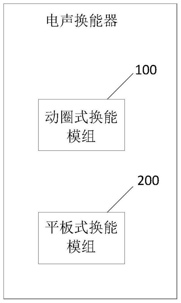
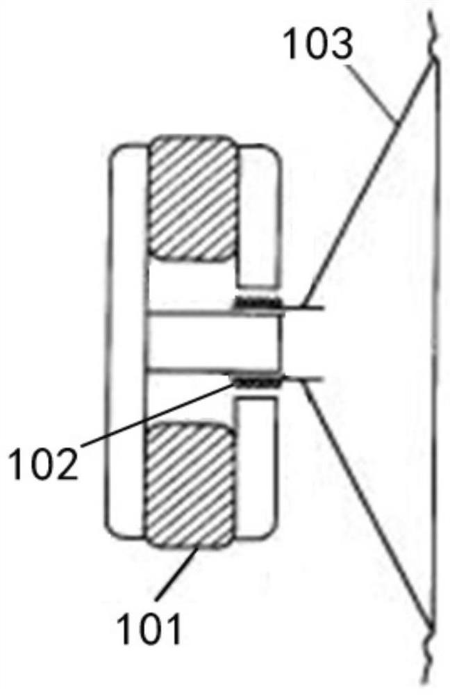
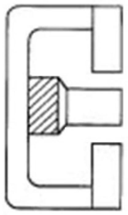
[0039] see figure 1 , figure 1 An electroacoustic transducer is shown. The electroacoustic transducer includes a moving coil transducer module 100 and a flat panel transducer module 200 . see figure 2 , figure 2 Shown is a moving coil transducer module 100 of an electroacoustic transducer. The moving coil transducer 100 includes a magnet 101 , a voice coil 102 and a vibrating element 103 . The voice coil 102 is placed between the magnetic poles of the magnet 101 and connected with the vibrating element 103 . The voice coil 102 is held in the center of the magnetic field in the gap of the magnetic circuit by a corrugated strut, and is input with audio current. see image 3 , image 3 Shown is the inner magnet magnetic circuit structure adopted by the magnet of the moving coil transducer module. The inner magnetic magnetic circuit structure includes a bowl-shaped soft magnetic structure, a cylindrical magnet is arranged in the center, a magnetic core is arranged on th...

Embodiment 2

[0047] This embodiment provides a moving-coil flat-panel composite loudspeaker, and the dynamic-coil flat-panel composite loudspeaker includes any one of the electro-acoustic transducers in Embodiment 1. The electroacoustic transducer includes a moving coil transducer module 100 and a flat panel transducer module 200 . The moving coil transducer 100 includes a magnet 101 , a voice coil 102 and a vibrating element 103 . The voice coil 102 is placed between the magnetic poles of the magnet 101 and connected with the vibrating element 103 . The voice coil 102 is held in the center of the magnetic field in the air gap of the magnetic circuit by a corrugated strut, and is input with audio current. The magnet 101 of the moving coil transducer module 100 adopts an inner magnetic type magnetic circuit structure or an outer magnetic type magnetic circuit structure. The magnet 101 adopts Alnico magnet or ferrite magnet. The vibrating element 103 of the dynamic transducing module 100 ...


PUM


Abstract

The invention relates to an electroacoustic transducer. The electroacoustic transducer comprises a moving coil type transduction module and a flat plate type transduction module, The moving coil typetransduction module comprises a magnet, a voice coil and a vibration element, wherein the voice coil is arranged between magnetic poles of the magnet and is connected with the vibration element. The flat plate type transduction module comprises a frame, a vibrating diaphragm and a flat plate magnet array. The periphery of the vibrating diaphragm is fixed on the frame and is provided with a coil, and a flat magnet array is arranged on one side or two sides of the vibrating diaphragm corresponding to the coil. The low-frequency response effect of the flat plate type loudspeaker can be improved,and the depth distance of the sound field of the loudspeaker is increased, so that the sound field of the loudspeaker is effectively improved, and the spatial layering sense is improved.

Description

technical field [0001] The invention relates to the application field of loudspeaker technology, in particular to an electroacoustic transducer and a moving coil flat panel composite loudspeaker. Background technique [0002] At present, HiFi electroacoustic speakers can be roughly divided into flat-panel speakers, dynamic speakers and electrostatic speakers according to the driving method. [0003] The most common speaker is a dynamic speaker, including a vibration system composed of a voice coil and a diaphragm, a magnetic circuit system composed of a permanent magnet, an iron core post, and a magnetic splint, and an auxiliary support system. When an alternating audio current is input to the voice coil, under the constant magnetic field of the permanent magnet, according to Faraday's law and the left-hand rule, the voice coil will be subjected to an alternating driving force, which will then drive the diaphragm to reciprocate. The vibration of the diaphragm drives the vib...

Claims


Application Information

Patent Timeline
Patent Type & Authority Patents(China)
IPC IPC(8): H04R9/06H04R9/02
Inventor 边仿
Owner HEAD DIRECT KUNSHAN CO LTD
Learn More