
Solenoid selection valve

A technology for selecting valves and solenoid valves, applied in the direction of sliding valves, valve details, multi-way valves, etc., to achieve the effects of easy operation, improving liquid applicability, and avoiding liquid leakage

Pending Publication Date: 2019-05-21
NANJING NAMOOR INSTR CO LTD
View PDF8 Cites 2 Cited by
  • Summary
  • Abstract
  • Description
  • Claims
  • Application Information

AI Technical Summary

Problems solved by technology

[0004] The purpose of the present invention is to solve the defects in the prior art and provide a selector valve with long service life and less leakage.

Method used


Image

  • Solenoid selection valve
  • Solenoid selection valve
  • Solenoid selection valve

Examples


Embodiment 1

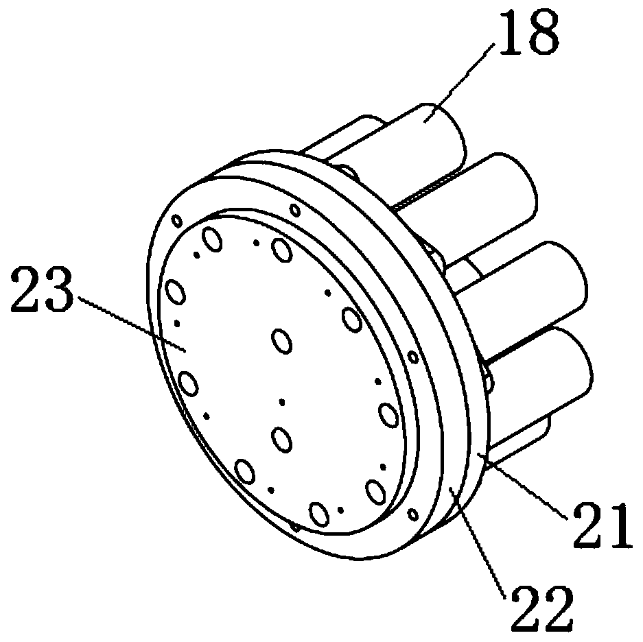
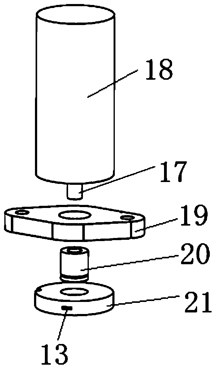
[0036] Such as figure 1 As shown, the electromagnetic selector valve of the present invention includes a valve body, and a plurality of one-to-one corresponding lifting electromagnetic valves 18 , electromagnetic valve fixing pieces, valve cores and valve core seats 21 . The valve body includes a valve body one 23 and a valve body two 22 bonded together.

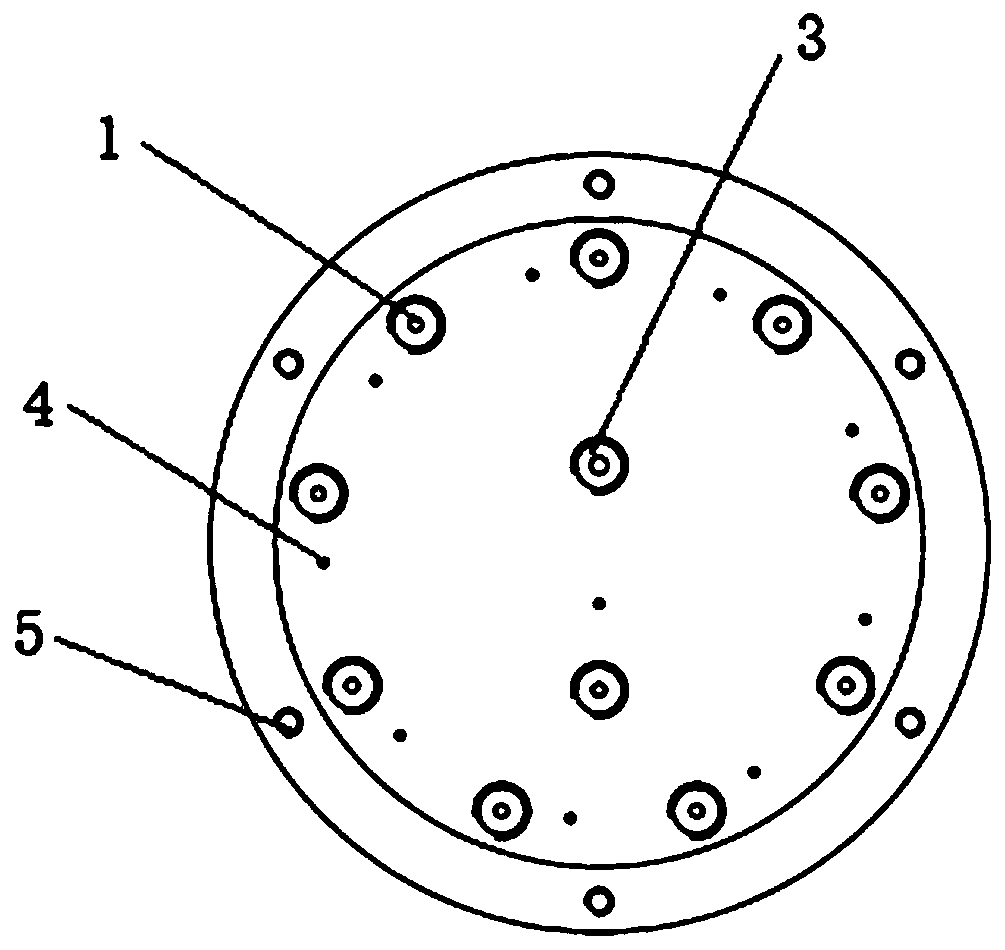
[0037] Take the ten-way valve as an example, such as image 3 As shown, the valve body 1 has ten liquid inlet holes 1, nine of which are equally distributed in a ring around the installation surface of the valve body 1, and the other is at the lower position in the middle of the valve surface. Correspondingly, the bonding surface of the valve body 1 is engraved with nine long and one short liquid circulation grooves 2 (such as Figure 4 As shown), the ten grooves 2 intersect at one point, which is set as the liquid outlet and communicates with the liquid outlet hole 3 provided on the mounting surface. A number of ventilat...

Embodiment 2

[0046] This embodiment is an example of a single-way solenoid valve, and the structural difference from the multi-way electromagnetic selector valve in Embodiment 1 is that the number of the valve core 410, the lifting solenoid valve 510, the solenoid valve fixing piece 511, and the valve core seat 310 are all one. The liquid inlet hole of valve body 1 is connected with the liquid inlet port of valve body 2, and the quantity is one; the liquid outlet hole of valve body 1 is connected with the liquid outlet of valve body 2, and the number is one; The bonding surface is no longer provided with grooves; other structures are consistent with those in Example 1, such as Figure 11 , Figure 12 shown.

[0047] Such as Figure 12 As shown, the specific working principle of the single-way solenoid valve is: the liquid enters the liquid circulation inlet hole 311 of the valve core seat from the valve body liquid inlet 111, when the solenoid valve lifts the valve core up, the passage o...


PUM


Abstract

The invention discloses a solenoid selection valve. The solenoid selection valve includes a first valve body, a second valve body, a valve core, a valve core seat and a lifting device, the first valvebody is stuck to the second valve body through a sticking face, a liquid outlet hole and a liquid inlet hole are formed in the mounting face of the first valve body, a liquid outlet and a liquid outlet are formed in the sticking face of the second valve body, a valve core seat mounting hole is formed in the mounting face, and the valve core seat is arranged in the valve core seat mounting hole; and the liquid inlet hole and the liquid outlet hole of the first valve body communicate with the liquid inlet and the liquid outlet of the second valve body correspondingly, a valve core mounting holeand liquid circulating holes penetrating in a radial mode and formed in the two sides of the valve core mounting hole are formed in the valve core seat, the liquid inlet and the liquid outlet of thesecond valve body communicate with the liquid circulating holes in the two sides respectively, the valve core is arranged in the valve core mounting hole through the lifting device, liquid circulatinggrooves are formed in the lower part of the valve core, and when the solenoid selection valve is in an opened state, the liquid circulating grooves communicate with the liquid circulating holes in the two sides of the valve core seat. According to the solenoid selection valve, the valve core is controlled to move up and down to control a channel switch in the valve body, and the selection switching of the channels can be effectively achieved.

Description

technical field [0001] The invention relates to the technical field of sampling valves, in particular to an electromagnetic selector valve. Background technique [0002] As a means of water quality detection, chemical analyzers have provided support for the development of environmental protection in my country to a large extent. Similar to manual detection, chemical analyzers use a variety of different reagents, and as analytical instruments, they should be automated as much as possible. Therefore, most analytical instruments will realize the automatic addition of various reagents by using a selection valve. [0003] At present, there are two kinds of selection valves widely used in the market. One is a mechanical selection valve, which changes the liquid inlet channel by rotating the valve face, so as to realize the selection of different reagents. After use, it is easy to cause valve surface wear, channel offset or liquid leakage; the other is the electromagnetic selecto...

Claims


Application Information

Patent Timeline
Patent Type & Authority Applications(China)
IPC IPC(8): F16K11/20F16K3/26F16K3/314F16K25/00F16K27/04
Inventor 洪樱伦黄进
Owner NANJING NAMOOR INSTR CO LTD
Learn More