
Unmanned ship unmanned aerial vehicle cooperative system and control method

A control method and technology for unmanned ships, applied in three-dimensional position/channel control, two-dimensional position/channel control, motor vehicles, etc. Program and other issues

Inactive Publication Date: 2019-05-21
JIMEI UNIV
View PDF6 Cites 17 Cited by
  • Summary
  • Abstract
  • Description
  • Claims
  • Application Information

AI Technical Summary

Problems solved by technology

Rotor UAVs have good flight flexibility and a wide field of vision, but when they work alone in remote sea areas, the image transmission effect is not good, and the battery life is limited (generally less than 30 minutes), and the round-trip charging will greatly increase the cost. Long-term continuous operation greatly limits its application range
Unmanned ships have strong endurance, large carrying capacity, and can carry a large number of instruments and equipment, but their vertical maneuvering functions are insufficient, and their sensing range is very limited
[0003] In the existing technology, although there are some assumptions about unmanned ships and UAVs, they have not provided a set of reasonable, effective and practical solutions.

Method used


Image

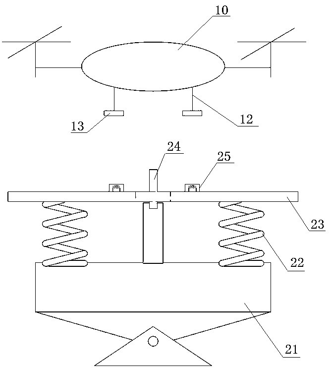
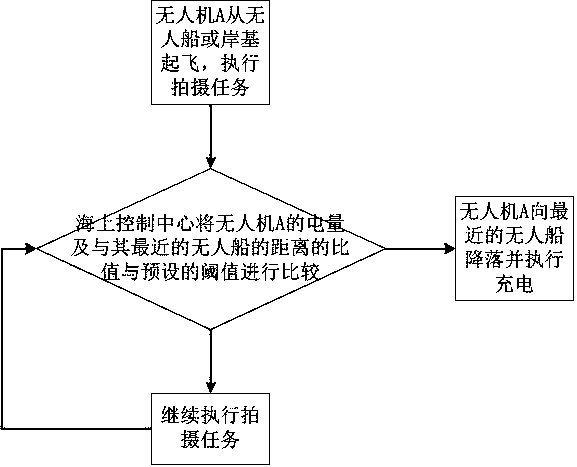
  • Unmanned ship unmanned aerial vehicle cooperative system and control method
  • Unmanned ship unmanned aerial vehicle cooperative system and control method
  • Unmanned ship unmanned aerial vehicle cooperative system and control method

Examples


Embodiment Construction

[0022] In order to make the features and advantages of this patent more obvious and easy to understand, the following special examples are described in detail as follows:

[0023] Such as figure 1 As shown, in the embodiment of the present invention, the overall system includes: multiple unmanned aerial vehicles, multiple unmanned ships and a control center, wherein the control center includes a sea control center and a shore-based control center. As the main control center, the shore-based control center is used to realize global scheduling, monitoring, data collection and collection, and undertake the same functions as the maritime control center in the near-shore area. In this embodiment, the maritime control center is generally set on the ship, and as the regional control center of the UAV and unmanned ship cluster, the maritime control center collects and masters the position coordinates of the UAV, the unmanned ship, and the location coordinates of the UAV. battery info...


PUM


Abstract

The invention provides an unmanned ship unmanned aerial vehicle cooperative system and a control method. The system comprises multiple unmanned aerial vehicles, multiple unmanned ships and a control center; the unmanned aerial vehicles are rotor wing unmanned aerial vehicles, and charging ports of the unmanned aerial vehicles are located at the lower sides of the vehicle bodies; each unmanned shipcomprises a halt platform and a plurality of unmanned aerial vehicle taking-off and landing charging devices arranged on the halt platform; the control center comprises an offshore control center anda shore based control center. The unmanned ships are defined as transfer and charging platforms of the unmanned aerial vehicles, meanwhile, the taking-off and landing charging integrated device design scheme is put forwards, and the device structure is simplified, multiple functions are achieved; for solving the problem of the unmanned aerial vehicles how to safely take off and land on jolting unmanned ship decks, a pan-tilt is adopted for isolating swing motion of ship bodies, a buffer device is used for avoiding collision when the unmanned aerial vehicles land on the decks, and a fixing device is used for being in cooperation with taking-off and landing of the unmanned aerial vehicles. The integrated control scheme for integrating the unmanned aerial vehicles, the unmanned ships, the offshore control center and the shore based control center is put forwards, and the synergic effect is brought into full play.

Description

technical field [0001] The invention belongs to the field of unmanned aerial vehicles, and in particular relates to an unmanned ship and unmanned aerial vehicle cooperation system and a control method. Background technique [0002] With the development of unmanned and intelligent technologies, unmanned ships and rotor drones are increasingly being used in various maritime applications, but they each have their own advantages and disadvantages. Rotor UAVs have good flight flexibility and a wide field of vision, but when they work alone in remote sea areas, the image transmission effect is not good, and the battery life is limited (generally less than 30 minutes), and the round-trip charging will greatly increase the cost. Long-term continuous operation greatly limits its application range. Unmanned ships have strong endurance, large carrying capacity, and can carry a large number of instruments and equipment, but their vertical maneuvering functions are insufficient, and the...

Claims


Application Information

Patent Timeline
IPC IPC(8): B64F1/00B63B35/00B60L53/00G05D1/10G05D1/02
CPCY02T10/70Y02T10/7072Y02T90/14
Inventor 周海峰张桂玲许大光王荣杰张兴杰陈景锋陈清林王佳宋佳声林忠华王新乡林世宪
Owner JIMEI UNIV
Learn More