
Top-mounted gasbag

An overhead, airbag technology, applied in pedestrian/occupant safety arrangement, vehicle safety arrangement, transportation and packaging, etc., can solve the problems of adverse effects of steering wheel, excessive bending of the driver's neck, high cost, and reduce neck injuries. Risky, easy to generalize, simple structure effect

Pending Publication Date: 2019-05-21
SHANGHAI LINGANG JOYSON SAFETY SYST CO LTD +1
View PDF9 Cites 3 Cited by
  • Summary
  • Abstract
  • Description
  • Claims
  • Application Information

AI Technical Summary

Problems solved by technology

[0003] The traditional driver's airbag is set in the steering wheel, which has an adverse effect on the design of the steering wheel. The patented design with the publication number DE19860827B4 eliminates this adverse effect
However, there are unresolved problems in its design in technical details, mainly three points: 1, the tension on the cloth sheet near the driver's side of the airbag bag is large, when the driver moves to the full airbag bag and squeezes the airbag, The airbag bag near the driver's chest is easily compressed, while the airbag bag near the head is not easily compressed, causing the driver's neck to bend backward excessively, posing a risk of injury
2. The gas generated by the gas generator cannot be quickly introduced into the air cavity of the main body, so there is an excessive impact force on the upper part of the air bag close to the gas generator, and there is a potential risk of damage to the air bag
3. The structure of the air bag is complex and the cost is high

Method used


Image

  • Top-mounted gasbag
  • Top-mounted gasbag
  • Top-mounted gasbag

Examples


Embodiment 1

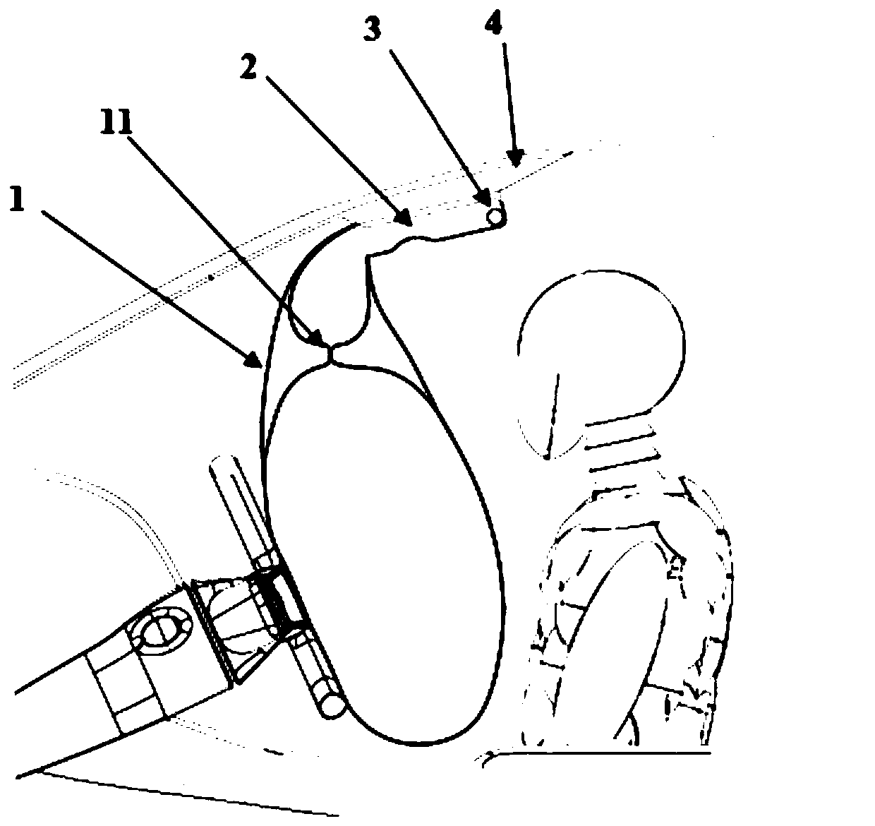
[0024] see figure 1 , the roof-mounted airbag in this example includes an airbag 1 , a housing 2 and a gas generator 3 . Gas generator 3 is contained in the inner one end of air bag 1, and gas generator 3 and air bag 1 are installed in the housing 2, and housing 2 is installed on the ceiling 4 in the car. A detachable part 11 is provided at the middle and upper part of the air bag 1 . The detachable part 11 divides the air bag 1 into the air bag upper chamber 12 and the air bag lower chamber 13, and the two sides of the detachable part 11 are provided with air guide parts 16, and the air bag upper chamber 12 and the air bag lower chamber 13 adopt air guide Department 16 Unicom. When the airbag 1 is inflated normally, the detachable part 11 maintains the initial complete state, and the overall shape of the airbag 1 remains intact, which is equivalent to the existing conventional top-mounted airbag, and the inflation and deployment of the airbag 1 is not affected.

[0025] se...

Embodiment 2

[0031] This example only illustrates the differences from Example 1, and the same parts as Example 1 will not be repeated.

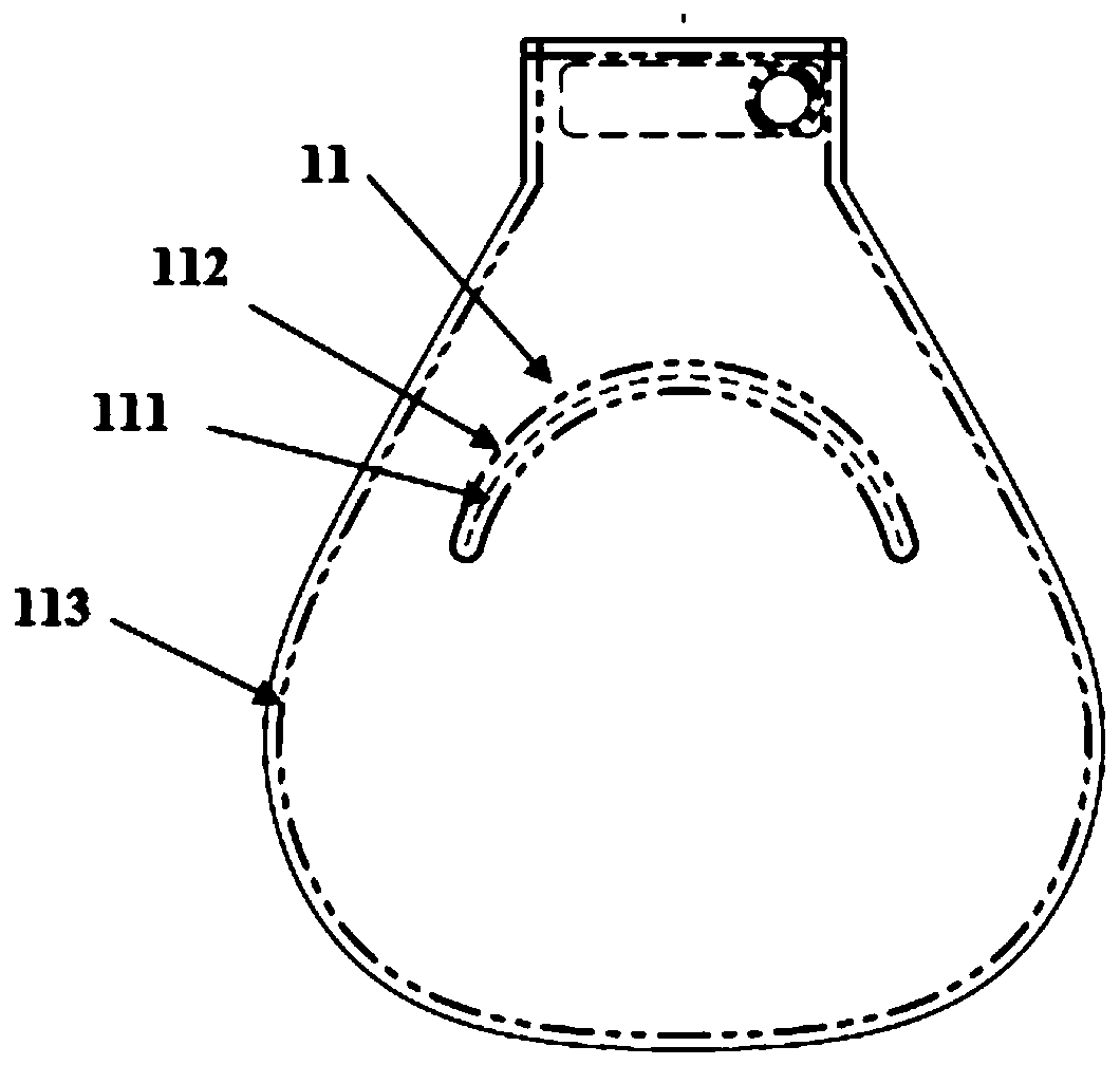
[0032] In this embodiment, the detachable part 11 is composed of a cutting line, a tearing line 111 and a sewing line 112 . The tear line 111 is arranged at the middle and upper part of the front main panel 14 of the airbag 1, that is, about 70% of the height. The cutting line is arranged at the middle and upper part of the rear main sheet 15 of the air bag 1, that is, about 70% of the height. The cutting line is completely disconnected, the cutting line and the tearing line 111 have the same shape and corresponding positions, the suture line 112 surrounds the cutting line and the tearing line 111, and the middle and upper parts of the front main piece 14 and the rear main piece 15 adopt the suture line 112 sutures.

[0033] In this embodiment, the function of the detachable part 11 is the same as that in Embodiment 1, and the working principle is simi...

Embodiment 3

[0036] This example only illustrates the differences from Example 1, and the same parts as Example 1 will not be repeated.

[0037] In this embodiment, the suture line 112 and the other suture line 113 between the front main piece 14 and the back main piece 15 are formed by interlaced weaving, or bonded by an adhesive.


PUM


Abstract

The invention relates to the technical field of passive safety devices, in particular to a top-mounted gasbag. The gasbag comprises a gasbag body, a gas generator and a shell, wherein the upper middlepart of the gasbag body is provided with a separable part, the separable part divides the gasbag body into an upper gasbag cavity and a lower gasbag cavity, the two sides of the separable part are provided with gas guide parts, and the upper gasbag cavity and the lower gasbag cavity are communicated by the gas guide parts. Compared with the prior art, the gasbag has the advantages that a top-mounted gasbag structure is designed, the separable part is arranged at the upper middle part of the gasbag body, and when a driver moves towards the gasbag filled with gas and squeezes the gasbag, the portion, close to the head of the driver, of the gasbag is compressed more easily, so that the risk of neck injuries caused by excessive backward bending of the neck of the driver is reduced; moreover,the gasbag adopts a simple design for cutting and sewing pieces and is simple in structure, low in cost and easy to popularize.

Description

technical field [0001] The invention relates to the technical field of passive safety devices, in particular to an overhead airbag. Background technique [0002] When a car collides, the airbag can provide effective buffer protection for the driver and passengers in the car. Publication No. DE19860827B4 discloses an airbag, which is installed in the roof of the vehicle. When a collision occurs, the airbag is inflated and falls from the roof in front of the driver to form a cushioning air cushion between the driver and the steering wheel. [0003] The traditional driver's airbag is arranged in the steering wheel, which has an adverse effect on the design of the steering wheel. The patented design with the publication number DE19860827B4 has eliminated this adverse effect. However, there are unresolved problems in its design in technical details, mainly three points: 1, the tension on the cloth sheet near the driver's side of the airbag bag is large, when the driver moves to ...

Claims


Application Information

Patent Timeline
IPC IPC(8): B60R21/214B60R21/231
Inventor 周厚林高尚君
Owner SHANGHAI LINGANG JOYSON SAFETY SYST CO LTD
Learn More