
Cabinet body of plate-type mortise-tenon assembly locking structure

A mortise and tenon and board-type technology, which is applied in the field of connection structure of board-type cabinet furniture, can solve problems such as shaking, increased shaking range, and poor stability

Pending Publication Date: 2019-05-17
陈国华
View PDF1 Cites 6 Cited by
  • Summary
  • Abstract
  • Description
  • Claims
  • Application Information

AI Technical Summary

Problems solved by technology

[0006] This patent only provides a connection structure between two vertical plates that is seated and inserted in the middle, which is commonly known as a T-shaped connection structure. Although this structure can realize a mortise and tenon connection without nails, due to the lower opening profile of the clamping groove Consistent with the profile of the large end of the tapered trapezoidal block, this clamping connection structure either has a large clamping resistance or a large gap, which will cause shaking after connection and poor stability, and the wooden material will be compressed after being squeezed. Deformation, the tenon will shrink, and the clamping groove space will become larger, so that the stability of the connection between the two vertical plates will be further deteriorated, the shaking will increase, and it will not be able to meet the accuracy requirements of multiple disassembly and assembly.

Method used


Image

  • Cabinet body of plate-type mortise-tenon assembly locking structure
  • Cabinet body of plate-type mortise-tenon assembly locking structure
  • Cabinet body of plate-type mortise-tenon assembly locking structure

Examples


Embodiment 1

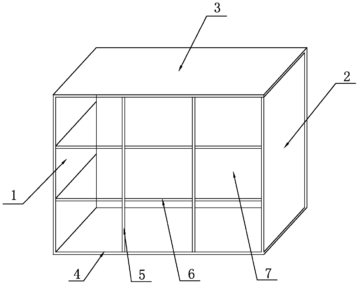
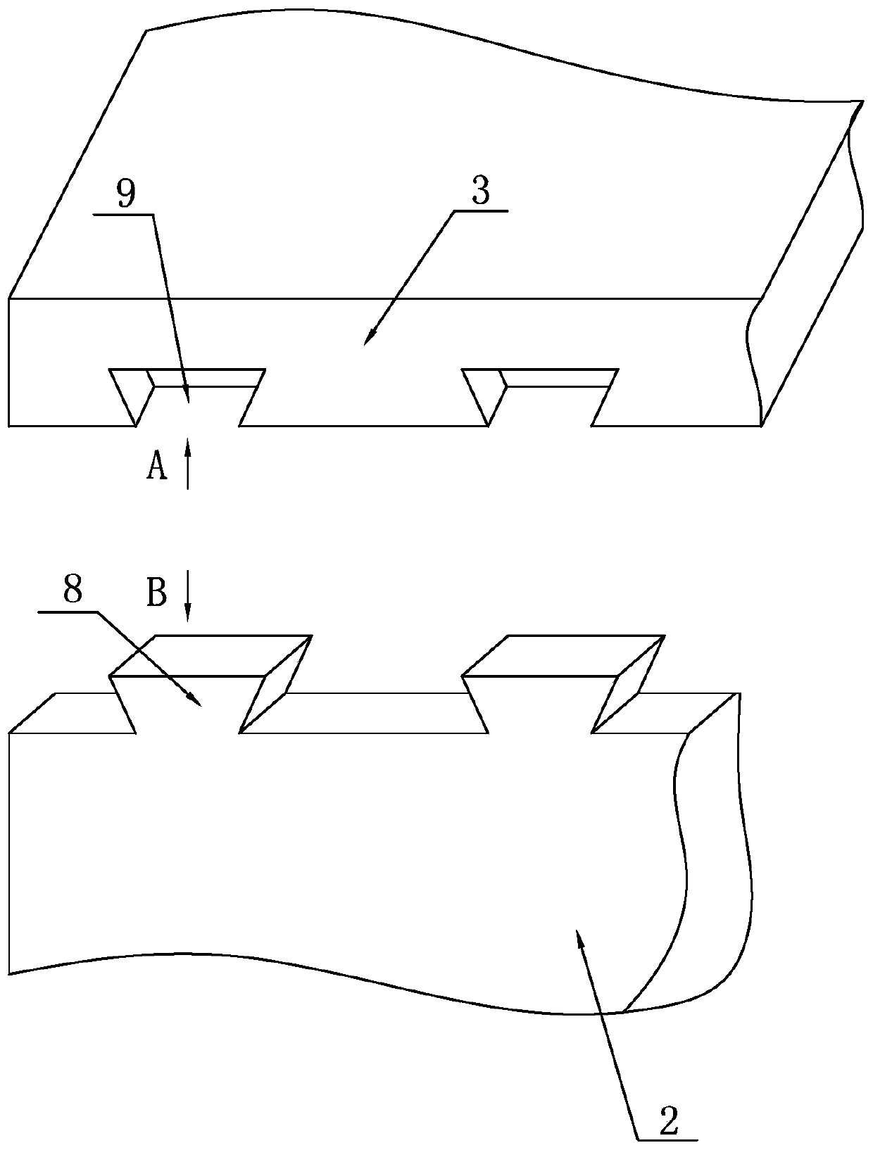
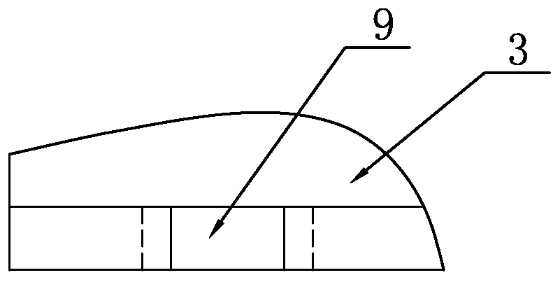
[0044] A panel type mortise and tenon assembly lock structure cabinet body, which is composed of a left side panel 1, a right side panel 2, a top panel 3, a bottom panel 4, two vertical partitions 5, two horizontal partitions 6 and a back panel 7 , the L-shaped fixed connection is realized between the left side plate 1, the right side plate 2, the top plate 3 and the bottom plate 4 through the dovetail tenon head 8 and the dovetail groove 9 mortise and tenon joint structure, and the height of the dovetail tenon head 8 is 80% of the plate thickness , the size, shape and depth of the dovetail groove 9 correspond to the dovetail tenon head 8, and the four are assembled into a cabinet frame; between the vertical partition 5 and the top board 3, the bottom board 4, the horizontal partition 6 and the left side board 1, The T-shaped fixed connection is realized between the right side panels 2 through the seat and gradually tightening plug-in engagement structure formed by the large an...

Embodiment 2

[0048] Embodiment 2: The difference from Embodiment 1 is that in the L-shaped fixed connection, two adjacent boards are spliced ​​at a 45-degree diagonal surface at the diagonal connection, so that the connection between the two cannot be seen from the outside. Mortise and tenon joint structure.


PUM


Abstract

The invention provides a cabinet body of a plate-type mortise-tenon assembly locking structure. F type fixed connection among a left side plate, a right side plate, a top plate and a baseplate is achieved through mortise-tenon meshing structures, and T type fixed connection between vertical separating plates or horizontal separating plates and a frame is achieved through a seating tapering and inserting meshing structure formed by large and small head section dovetail mortises, seating grooves and tapering dovetail grooves; H type fixed connection between the horizontal separating plates and the vertical separating plates or the right and left side plates is achieved through a guide rail inserting structure; and backplane slots are formed in the same plane of the back sides of the left side plate, the right side plate and the baseplate of the frame, and a backplane is inserted into the backplane slots. A dovetail tenon is designed as a bidirectional trapezoidal cube structure; not onlycan the mortise-tenon joint is achieved, but also the installation and removal resistance can be reduced; the installation and removal are convenient, and a clearance of clamping connection between two plates can be removed; shaking is eliminated, and the stability is high; and the accuracy after repeated installation and removal is improved.

Description

Technical field: [0001] The invention relates to an assembly and connection structure of panel furniture, in particular to the connection structure of panel furniture. Background technique: [0002] The cabinet furniture includes left side board, right side board, top board, bottom board, back board, vertical partition and horizontal partition. The left side board, right side board, top board and bottom board are L-shaped connections. Between the straight partition and the top and bottom boards, between the horizontal partition and the left and right side boards are all T-shaped connections, between two adjacent vertical partitions and horizontal partitions, or between two adjacent horizontal partitions Both are cross-shaped connections with the vertical partitions. [0003] At present, in the split-assembled panel cabinet furniture, the connection method between the panels is generally connected by a combined lock piece, which has low connection strength, poor stability, a...

Claims


Application Information

Patent Timeline
IPC IPC(8): F16B5/00F16B12/12A47B47/00A47B96/20
Inventor 陈国华
Owner 陈国华
Learn More