Rail robot power driving mechanism and system and rail robot

A rail robot and power-driven technology, applied in the field of robotics, can solve the problems of inconvenient adjustment of driving wheel friction, constant driving energy consumption, poor climbing ability, etc., to improve environmental adaptability, avoid wear, and improve use The effect of longevity

Pending Publication Date: 2019-05-17
深圳昱拓智能有限公司
View PDF6 Cites 11 Cited by
  • Summary
  • Abstract
  • Description
  • Claims
  • Application Information

AI Technical Summary

Problems solved by technology

However, the existing rail robot power drive mechanism is driven by friction wheels, which has disadvantages such as poor climbing ability, constant energy consumption for climbing and linear track walking, inconvenient adjustment of the friction force of the driving wheel, and unstable operation.

Method used


Image

  • Rail robot power driving mechanism and system and rail robot
  • Rail robot power driving mechanism and system and rail robot
  • Rail robot power driving mechanism and system and rail robot

Examples


Embodiment 1

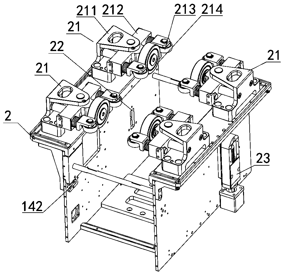
[0028] like figure 1 and figure 2 As shown, the orbital robot power drive mechanism of the present embodiment comprises an orbital walking driving device 1 and a main frame 2, the main frame 2 is provided with a guide wheel assembly 21 and a pair of slide grooves 22, and the two sides of the orbital traveling driving device 1 are provided with There is a connecting column 11 protruding laterally. The connecting column 11 is slidably arranged in the sliding groove 22. A track installation position is formed between the guide wheel assembly 21 and the track running part 12 of the track running drive device 1. One end of the sliding groove 22 is provided with a The connecting column 11 is pressed against the pressure regulating device 23 for adjusting the frictional force of the rail installation position. Since both sides of the track driving device 1 are pressed against the pressure regulating device 23, on the one hand, the pressure regulating device can be adjusted accordin...

Embodiment 2

[0052] In this embodiment, the stroke adjustment assembly is a manual stroke adjustment assembly. Compared with the electric stroke adjustment assembly of Embodiment 1, the manual stroke adjustment assembly is simpler in structure and lower in cost, and it is quite more suitable for a relatively single track structure, such as all tracks 3 with a fixed slope, or all of which are specific arcs shaped structure track 3 and so on. like Figure 8 As shown, the manual stroke adjustment assembly includes a fixed screw sleeve 237, and the fixed screw sleeve 237 is sleeved with an adjusting bolt that is threaded. The adjusting bolt is connected to the spring adjusting plate 233. By rotating the adjusting bolt, the position of the spring adjusting plate 233 / The stroke changes, and then the pressure can be adjusted according to the needs to meet the climbing ability of the ramp or the energy saving of the straight track; it is also possible to use different walking pressures for the i...


PUM


Abstract

The invention discloses a rail robot power driving mechanism and system and a rail robot. The power driving mechanism comprises a rail travelling driving device and a main frame, a guiding wheel assembly and a pair of sliding grooves are formed in the main frame, connecting columns extending horizontally are arranged on the two sides of the rail travelling driving device, the connecting columns are slidably formed in sliding grooves, a rail mounting station is formed between the guiding wheel assembly and a rail travelling component of the rail travelling driving device, a pressure adjusting device for adjusting the friction of the rail mounting station is arranged at one end of each sliding groove, and the connecting columns are ejected or supported on the pressure adjusting devices. According to the rail robot power driving mechanism, the friction adjustment is achieved according to the pressure of a slope adjusting and pressure adjusting device, the driving ability of climbing the steep slope can be improved, the driving energy consumption of a flat straight rail can be reduced, the two pressure adjusting devices can be adjusted so as to reduce the distortion degree of steeringtravelling with different pressures, the amount of bend travelling wear is reduced, the service life of driving wheels is prolonged, and the environmental adaptability of the power driving mechanism is greatly improved.

Description

technical field [0001] The invention relates to the field of robots, in particular to an orbital robot power drive mechanism, a system and an orbital robot. Background technique [0002] Rail robots (track-type inspection robots) can be used in power distribution rooms, comprehensive pipe galleries, power plant coal transportation trestles, boiler rooms, factories, large supermarkets and other places. With the advocacy of national intelligent manufacturing, various intelligent inspection robots emerge in endlessly. Among them, orbital robots are more and more widely used due to their stable and reliable operating lines, wide monitoring range, and simple and convenient operation and control. As the most important mechanism of the orbital robot, the power drive mechanism of the orbital robot is also particularly important in its design. However, the existing rail robot power drive mechanism is driven by friction wheels, which has disadvantages such as poor climbing ability, c...

Claims


Application Information

Patent Timeline
Patent Type & Authority Applications(China)
IPC IPC(8): B25J5/02
Inventor 阳立华刘智勇李哲樊绍胜黄明星
Owner 深圳昱拓智能有限公司
Why Eureka
Try Eureka