Magnetic nut locking mechanism

A nut lock, magnetic suction technology, applied in metal processing equipment, metal processing, manufacturing tools and other directions, can solve the problems of reducing work efficiency, unable to lock the screw and nut, fixing the angle of the nut locking, etc., to improve work efficiency. Effect

Active Publication Date: 2019-07-05
QUICK INTELLIGENT EQUIP CO LTD
View PDF7 Cites 0 Cited by
  • Summary
  • Abstract
  • Description
  • Claims
  • Application Information

AI Technical Summary

Problems solved by technology

[0003] The technical problem to be solved by the present invention is: in order to solve the problem that the nut locking angle of the existing nut locking mechanism is fixed, the nut locking cannot be performed on the inclined screw rod, and the manual operation is often used, which reduces the work efficiency. Provides a magnetic suction nut locking mechanism

Method used


Image

  • Magnetic nut locking mechanism
  • Magnetic nut locking mechanism
  • Magnetic nut locking mechanism

Examples


Embodiment Construction

[0030] The present invention is described in further detail now in conjunction with accompanying drawing. These drawings are all simplified schematic diagrams, which only illustrate the basic structure of the present invention in a schematic manner, so they only show the configurations related to the present invention.

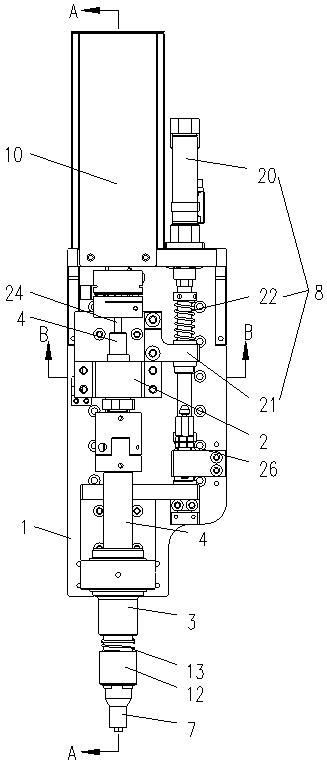
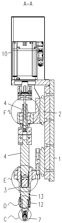
[0031] Such as Figure 1-9 As shown, a magnetic suction nut locking mechanism includes a base 1, a sliding seat 2, a sheath 3, a first rotating shaft 4, a second rotating shaft 5, a first spring 6 and a clip 7, and the sliding seat 2 slides Set on the base 1, the base 1 is provided with a first driving device 8 for driving the sliding seat 2 to slide, one end of the first rotating shaft 4 is rotatably arranged on the sliding seat 2, and the other end of the first rotating shaft 4 A universal joint 9 is provided between one end and the second rotating shaft 5, and the base 1 is provided with a second driving device 10 for driving the first rotating shaft 4 to ...


PUM


Abstract

The present invention relates to the technical field of nut locking equipment, in particular to a magnetic nut locking mechanism, which includes a base, a sliding seat, a sheath, a first rotating shaft, a second rotating shaft, a first spring and a clip. The seat is slidably arranged on the base, and the base is provided with a first drive device for driving the sliding seat to slide, one end of the first rotating shaft is rotatably arranged on the sliding seat, the other end of the first rotating shaft and the second rotating shaft There is a universal coupling between them, the base is provided with a second driving device for driving the first rotating shaft to rotate, the first spring is sleeved on the universal coupling, and the magnetic suction nut lock of the present invention When the auxiliary mechanism is in use, the universal coupling between the first rotating shaft and the second rotating shaft protrudes from the sheath, so as to realize the universal rotating shaft of the second rotating shaft, so that the locking mechanism is suitable for when the screw rod is in an inclined state. Nut lock pay, improve work efficiency.

Description

technical field [0001] The invention relates to the technical field of nut locking devices, in particular to a magnetic suction nut locking mechanism. Background technique [0002] The threaded connection between the nut and the screw is already a connection method for many devices to realize the fixed connection. It is easy to install and easy to disassemble. Usually people thread the nuts to the screw rods manually, which is inefficient and time-consuming. In order to improve work efficiency, the nuts are locked by the locking mechanism, and the installed screw rods are caused by installation errors or external forces. The screw rods are inclined to each other, and the nut locking angle of the existing nut locking mechanism is fixed, so it is impossible to perform nut locking on the inclined screw rods, and the operation is usually performed manually, which reduces the work efficiency. Contents of the invention [0003] The technical problem to be solved by the present ...

Claims


Application Information

Patent Timeline
Patent Type & Authority Patents(China)
IPC IPC(8): B23P19/06
Inventor 李旺青朱续纬倪彪
Owner QUICK INTELLIGENT EQUIP CO LTD
Why Eureka
Try Eureka