
Grinding system and grinding method

A grinding and grinding disc technology, which is applied in the direction of grinding slides, grinding racks, grinding bed, etc., can solve the problems that the workpiece to be ground is not easy to be installed automatically, and the output shaft of the grinding motor is easily damaged due to large force, so as to reduce the The risk of bending, the effect of simplifying the structure and shortening the stroke

Active Publication Date: 2020-06-16
NEWAY VALVE SUZHOU
View PDF8 Cites 0 Cited by
  • Summary
  • Abstract
  • Description
  • Claims
  • Application Information

AI Technical Summary

Problems solved by technology

[0008] Therefore, the technical problem to be solved by the present invention is to overcome the defects in the prior art that the workpiece to be ground is not easy to be automatically installed and the output shaft of the grinding motor is easily damaged due to high force, thereby providing a grinding system and grinding method

Method used


Image

  • Grinding system and grinding method
  • Grinding system and grinding method
  • Grinding system and grinding method

Examples


Embodiment 1

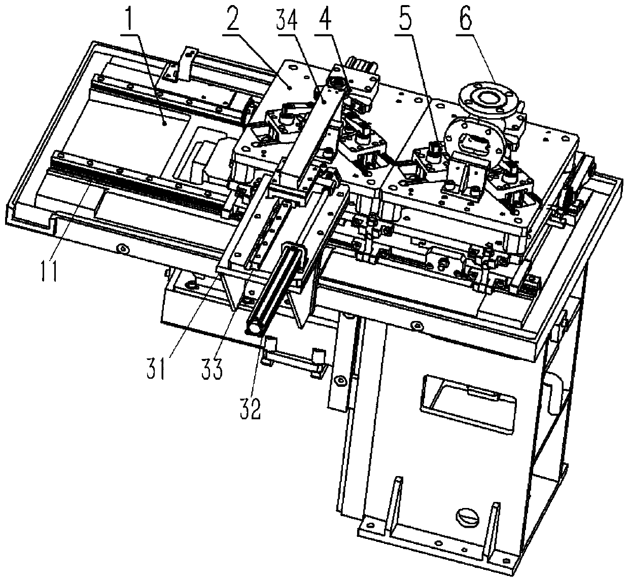
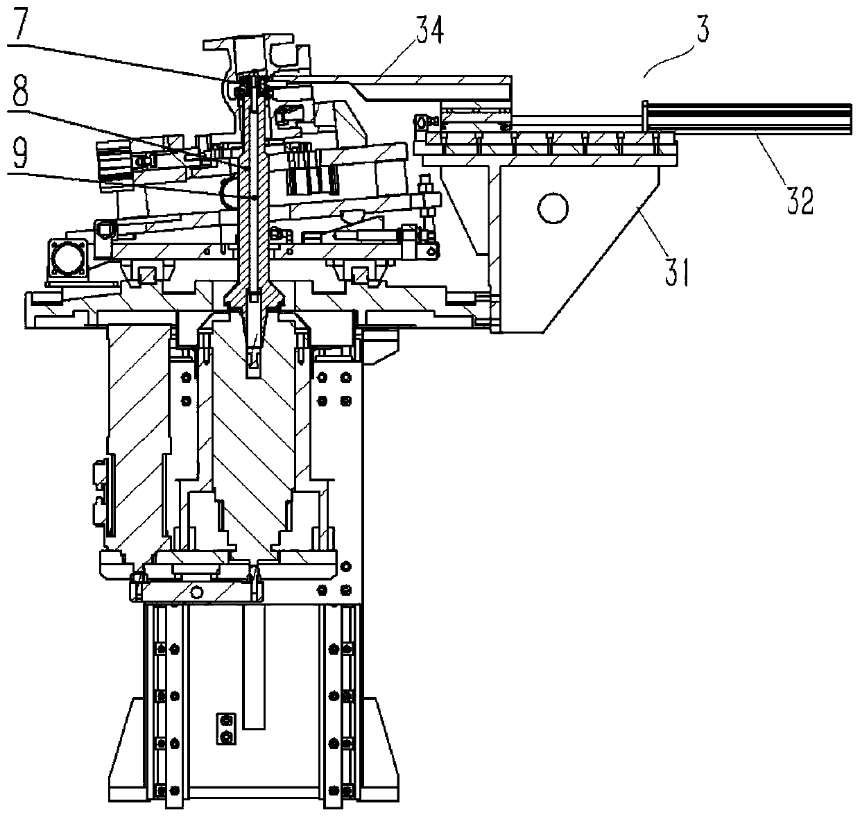
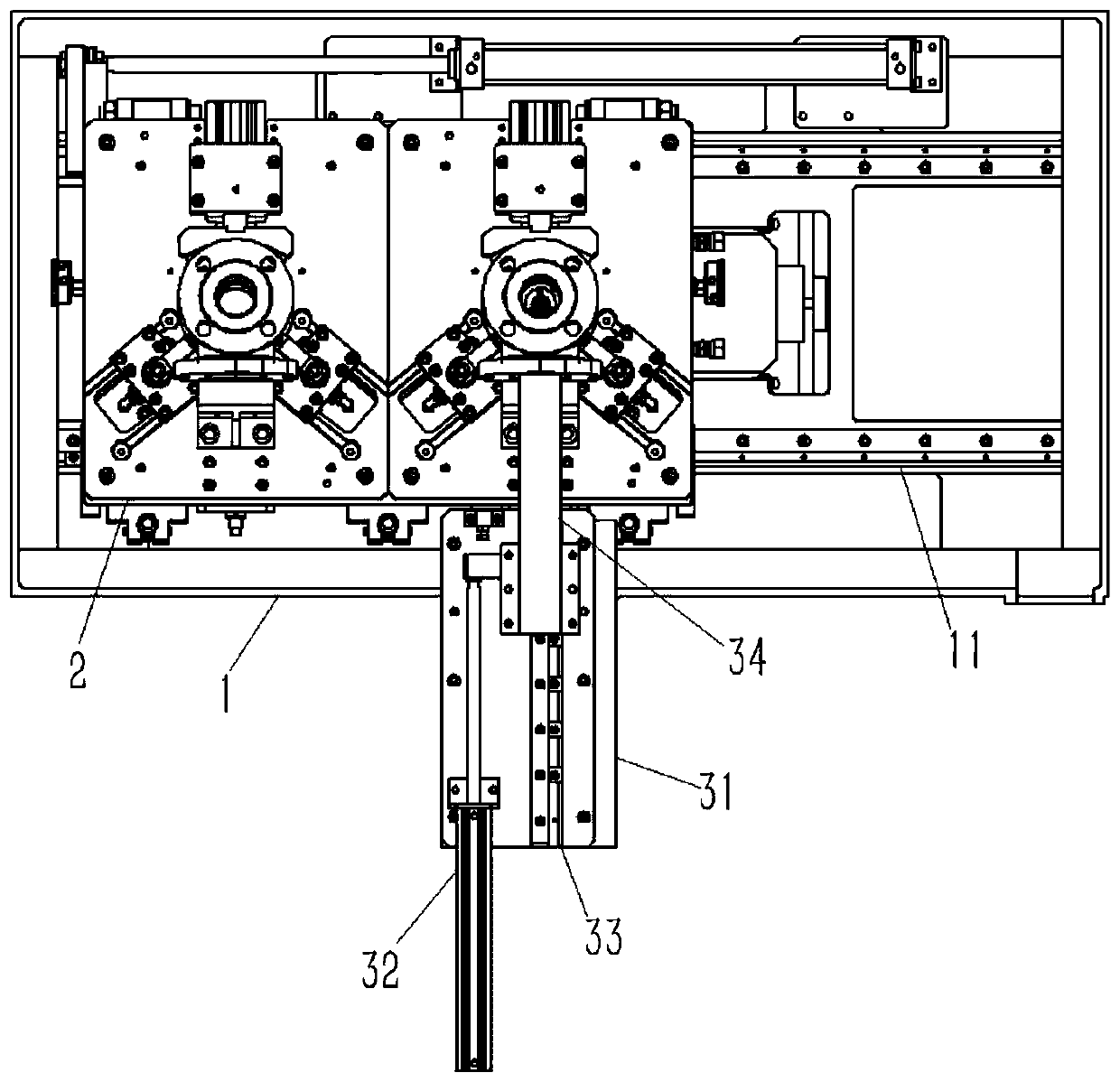
[0045] Such as Figure 1-3 As shown, this embodiment provides a grinding system suitable for grinding the inner wall of the object to be ground, including: a frame 1;

[0046] At least one workbench 2 is provided with a fixture 5, the fixture 5 is used for the installation and positioning of the object 6 to be ground, and the workbench 2 is provided with a via hole;

[0047] The grinding disc 4 is suitable for being transported into the inner cavity of the object to be ground 6;

[0048] The rotating main shaft 8 is arranged on the frame 1 in a liftable manner, and the rotating main shaft 8 has a first working position and a standby position, wherein the standby position is a position where the rotating main shaft 8 is under the workbench 2, and the first The working position is the position where the rotating spindle 8 extends upward through the through hole into the inner cavity to install or remove the grinding disc 4;

[0049]The grinding disc automatic installation mech...

Embodiment 2

[0062] The present embodiment provides a kind of grinding method, adopts the grinding system in embodiment 1, comprises the following steps:

[0063] Clamping the object to be ground 6;

[0064] Transport the grinding disc 4 to the inner cavity of the object to be ground 6, and drive the rotating main shaft 8 to pass through the workbench 2 from the standby position and enter the first working position of the inner cavity of the object to be ground 6, and install the grinding disc 4 on the rotating main shaft the upper end of 8;

[0065] Move to the area to be ground for grinding;

[0066] After grinding, return to the first working position for disassembly, and the rotating main shaft 8 descends to the standby position.

[0067] In the above-mentioned grinding method, the object to be ground 6 is positioned and installed by the fixture 5, and the installation method is preferably pneumatic clamping; The installation method is manual or automatic; then press the start butto...


PUM


Abstract

The invention relates to the technical field of grinding machines, in particular to a grinding system and a grinding method. The grinding system comprises a workbench provided with a via hole, a grinding disc suitable for being conveyed into an inner cavity of a to-be-ground object, a rotating main shaft and a grinding disc automatic installing mechanism; the rotating main shaft has a first working position and a standby position, wherein the standby position is the position of the rotating main shaft located below the workbench, and the first working position is the position that the rotatingmain shaft upwards penetrates through the via hole to extend into the inner cavity to install or detach the grinding disc; the rotating main shaft is located below the workbench, the stroke of the rotating main shaft is shortened, loading and unloading of a workpiece are facilitated, and influences caused by the fact that a driving component is located above a workbench face on layout of a workpiece loading and unloading mechanical arm on the workbench are avoided; and the rotating main shaft conducts pulling from top to bottom to conduct grinding, a grinding head is provided with downward pulling force, the risk of bending due to large stress of a grinding shaft is reduced, and the structure of the driving end is simplified.

Description

technical field [0001] The invention relates to the technical field of grinding machines, in particular to a grinding system and a grinding method. Background technique [0002] The valve is the control part in the fluid conveying system. The wedge gate valve is one of the valves. It is widely used in petrochemical, thermal power plants and other oil and water vapor pipelines to connect or cut off the medium in the pipeline. device. The sealing surface of the valve body is the mating surface between the interior of the valve and the valve core. [0003] Grinding machines are used in high-precision fields such as end face grinding of metal sealing surfaces of valves in the valve manufacturing process, and have been widely used in industry. The grinding of the sealing surface of traditional wedge gate valve body is mostly done by radial drilling machine, which is a laborious work with low production efficiency, and the grinding quality mainly depends on the technical level o...

Claims


Application Information

Patent Timeline
Patent Type & Authority Patents(China)
IPC IPC(8): B24B15/04B24B41/04B24B51/00B24B41/02B24B41/00
Inventor 富文华丁邦建孙长春
Owner NEWAY VALVE SUZHOU
Learn More