A precise positioning rail drill

A precise positioning and rail technology, applied in the field of rail transit, can solve the problems of low safety and stability, uneven force, easy to slip, etc., achieve good safety and stability, prolong the service life and improve the working accuracy Effect

Active Publication Date: 2020-11-03
聚隆创环保科技(嘉兴)有限公司
View PDF8 Cites 0 Cited by
  • Summary
  • Abstract
  • Description
  • Claims
  • Application Information

AI Technical Summary

Problems solved by technology

[0006] The invention provides a precisely positioned rail drill, which has the advantages of high positioning accuracy of the drill bit, no tilting of the drill bit when installed and fixed, reduced wear of the drill bit and high stability, and solves the problem of the existing When the manual drill is positioned and installed, it is very easy to tilt due to shaking, which eventually leads to poor hole position accuracy on the rail, and when the drill bit is working tilted, due to the uneven force of the drill bit, the wear of the drill bit is aggravated At the same time, when the inclined drill bit is stressed, it is very easy to slip, and the safety and stability are low.

Method used


Image

  • A precise positioning rail drill
  • A precise positioning rail drill
  • A precise positioning rail drill

Examples


Embodiment Construction

[0025] The following will clearly and completely describe the technical solutions in the embodiments of the present invention with reference to the accompanying drawings in the embodiments of the present invention. Obviously, the described embodiments are only some of the embodiments of the present invention, not all of them. Based on the embodiments of the present invention, all other embodiments obtained by persons of ordinary skill in the art without making creative efforts belong to the protection scope of the present invention.

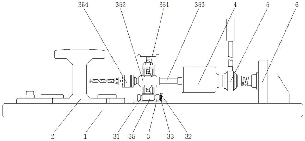
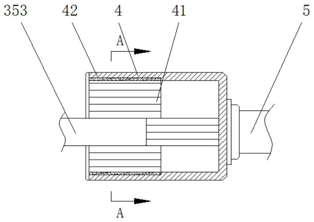
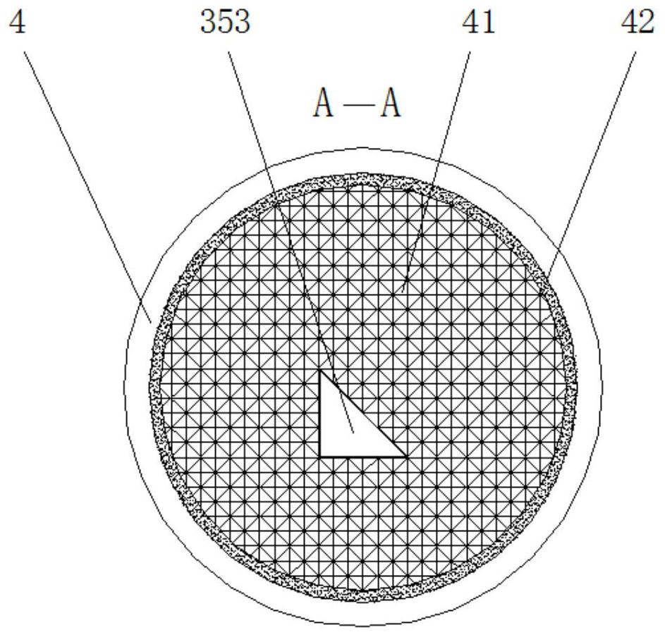
[0026] see Figure 1-5 , a rail drill with precise positioning, including a support base 1, a rail 2, a fixed support frame 3, a clamping sleeve 4, a ratchet handle 5 and a fixed table 6, the side of the top of the support base 1 and the rail 2 The bottom end is clamped, the middle part of the top of the support base 1 is fixedly connected to the bottom end of the fixed support frame 3, one side of the middle part of the fixed support frame 3 is ...


PUM


Abstract

The invention relates to the technical field of rail transit, and discloses a precisely positioned ratchet drill for a rail. The precisely positioned ratchet drill for the rail includes a support base, the rail, a fixed support frame, a clamping sleeve, a ratchet handle and a fixed table. One side of the top end of the support base is connected to the rail in a clamped mode, the top end of the support base is fixedly connected to the bottom end of the fixed support frame, the clamping sleeve is arranged on one side of the middle of the fixed support frame, and the ratchet handle is fixedly mounted on the other side of the exterior of the clamping sleeve. According to the precisely positioned ratchet drill for the rail, through the arrangement of the clamping sleeve, the ratchet handle is used for driving the whole of the clamping sleeve to move forward after precise positioning of a drill bit; and meanwhile, a movable connecting rod squeezes a magnetic blocking rod and enables the magnetic blocking rod to move backwards, a gap with the same size as the movable connecting rod is reserved to clamp the movable connecting rod, so that the clamping sleeve can effectively clamp when theposition of the drill bit is adjusted within a certain range, and furthermore the precisely positioned ratchet drill can drill the rail.

Description

technical field [0001] The invention relates to the technical field of rail transportation, in particular to a precisely positioned rail drill. Background technique [0002] The rail hand pull drill is mainly used for re-drilling the laid rails in remote areas without electricity and oil. It has the advantages of convenient loading and unloading, small size, light weight and easy portability, and is widely used in railways. maintenance department. [0003] When drilling on the laid track, it is necessary to lay the drilling machine flat between the two rails, the drill bit bears against the drilling position, and the feed head at the other end is on the mounting frame, turn the feed handle to make it firmly Fix it, and finally turn the joystick to start drilling. [0004] However, when positioning and fixing the mounting frame, it is very easy to shake, which will cause the position of the lever drill bit to deviate from the position of the rail positioning hole, resulting...

Claims


Application Information

Patent Timeline
Patent Type & Authority Patents(China)
IPC IPC(8): E01B31/06
Inventor 不公告发明人
Owner 聚隆创环保科技(嘉兴)有限公司
Why Eureka
Try Eureka