
Mold for water dropper forming

A mold and dripper technology, which is applied in the field of dripper molding molds, can solve problems such as increased workload, uneven heating of molds, and influence on mold closing, so as to save mold costs, reduce material costs, and avoid blockage of flow channels Effect

Pending Publication Date: 2019-05-07
LAIWU SPRING RAIN DRIP IRRIGATION TECH
View PDF0 Cites 3 Cited by
  • Summary
  • Abstract
  • Description
  • Claims
  • Application Information

AI Technical Summary

Problems solved by technology

[0003] However, the existing traditional molds have the following shortcomings: 1) The traditional mold core adopts a whole-plate structure, and the mold core needs to be replaced as a whole after the mold core is worn out, resulting in a great waste of mold steel and high replacement costs. In addition, the whole-plate structure mold During the use of the core, it is easy to cause serious wear and tear; 2) The traditional mold core adopts a recessed structure, that is, the core is embedded in the substrate, and the recessed structure is prone to poor heat dissipation, resulting in heat accumulation, which is not conducive to dripper products Cooling; 3) Most of the existing molds use semi-hot runners or cold runners, and the mold needs to be heated from the outside during use, resulting in uneven heating of the mold and large power consumption; 4) The existing molds are prone to gas retention when closing the mold. Affect mold clamping and reduce production efficiency
5) The dripper products produced by the existing dripper molds will have a large material bar on the top, and the dripper products need to be cleaned, which increases the workload and causes waste of raw materials, resulting in increased costs

Method used


Image

  • Mold for water dropper forming
  • Mold for water dropper forming

Examples


Embodiment 1

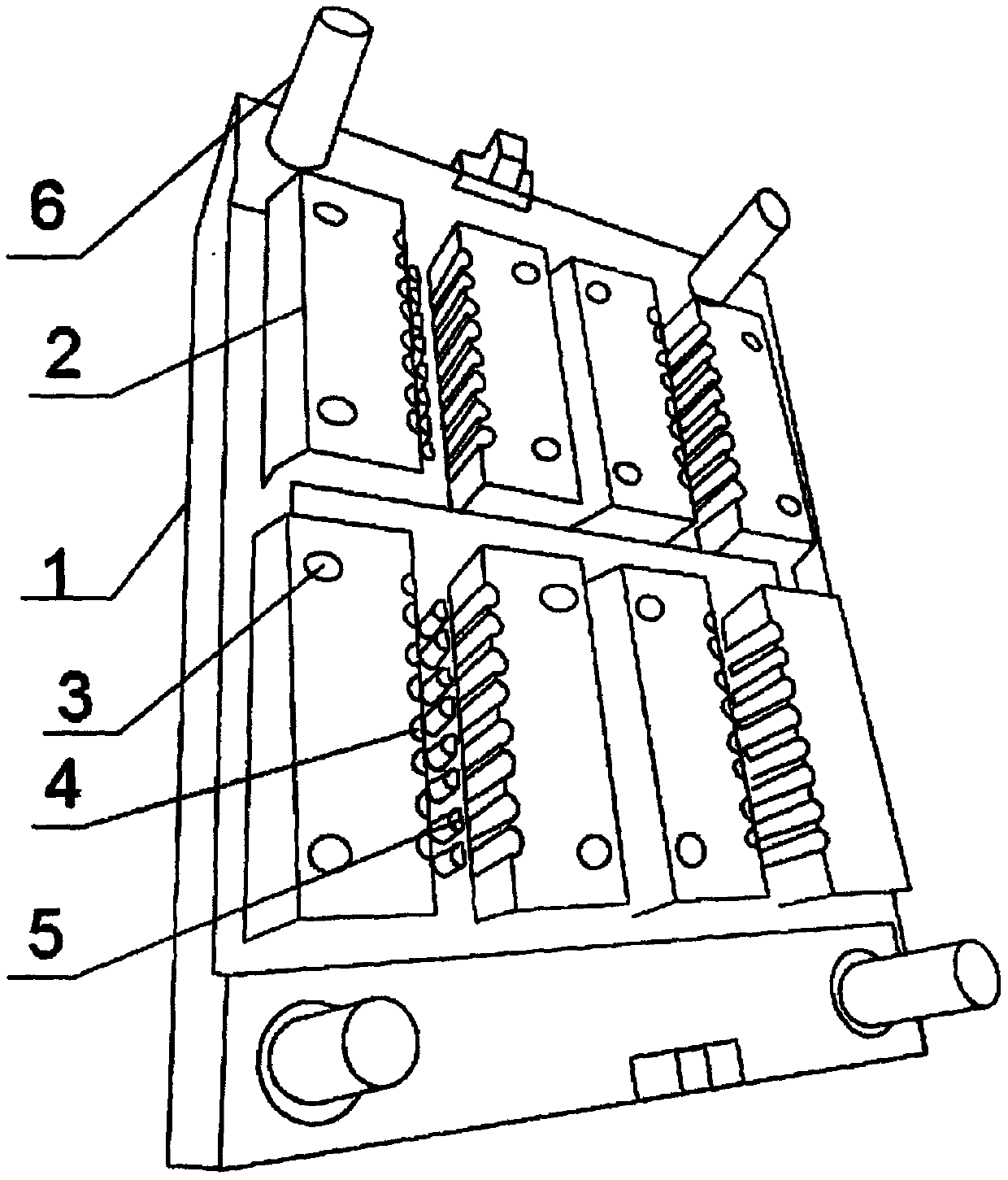
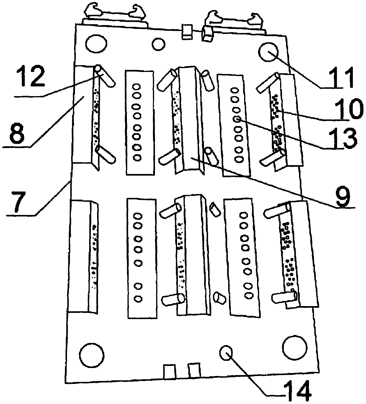
[0021] Such as figure 1 , 2 As shown, a mold for dripper molding of the present invention includes a mold A main body and a mold B main body that can be fastened together, and the mold A main body includes A base 1 and four groups that are independent and protrudingly installed on the A base. The mold core 2 above 1, four groups of mold cores 2 are arranged in two rows, and each row has two groups of mold cores 2, and each group of mold cores 2 includes two rectangular cores spaced side by side, and the two cores are opposite to each other. There are 8 dripper cavities 4 with a semicircular cross-section and vertical penetration on the sides, and the dripper cavities 4 on the two sides are opposite to each other and between each two opposing dripper cavities 4 A cylindrical core 5 is provided, and each core body is provided with two positioning holes 3, and the four corners of the A base 1 are provided with four positioning columns 6; the B mold body includes a B base 7 and a...


PUM


Abstract

The invention discloses a mold for water dropper forming. An A mold body and a B mold body which can be buckled are included; the A mold body comprises an A base and four sets of independent mold cores installed above the A base in a protruding manner; the four sets of mold cores are arranged into two rows, and two sets of mold cores are arranged in each row; each set of mold core comprises two oblong core bodies side by side in a left-right spaced manner, and the two opposite side edges of every two core bodies are each provided with eight up-down through water dropper mold cavities with semicircular cross sections; the water dropper mold cavities on the two side edges are opposite left and right, and a cylinder mold core is arranged between every two opposite water dropper mold cavities;each core body is provided with two positioning small holes, and four positioning large columns are arranged at the four corners of the A base; and the B mold body comprises a B base and six positioning sealing bases fixed to the B base. The mold cost is saved, it is avoided that after whole plate structure mold core abrasion, a mold core is replaced as a whole, and the production efficiency is improved.

Description

technical field [0001] The invention belongs to the technical field of hot runner moulds, in particular to a mold for dripper molding. Background technique [0002] The hot runner mold is a mold that uses a heating device to keep the melt in the runner from solidifying. Because it has a shorter forming cycle than traditional molds and saves more raw materials, hot runner molds are widely used in various industrially developed countries and regions in the world today. [0003] However, the existing traditional molds have the following shortcomings: 1) The traditional mold core adopts a whole-plate structure, and the mold core needs to be replaced as a whole after the mold core is worn out, resulting in a great waste of mold steel and high replacement costs. In addition, the whole-plate structure mold During the use of the core, it is easy to cause serious wear and tear; 2) The traditional mold core adopts a recessed structure, that is, the core is embedded in the substrate, ...

Claims


Application Information

Patent Timeline
IPC IPC(8): B29C45/34B29C45/27B29C45/73
Inventor 张亮李传胜
Owner LAIWU SPRING RAIN DRIP IRRIGATION TECH
Learn More