
Multi-directional traction frame for closed reduction of tibial fracture

A technology of traction frame and tibia, which is applied in the direction of fixators and external fixators, can solve the problems of large trauma, troublesome treatment of tibial fractures, unfavorable recovery of patients, etc., and achieve large bending degree, good traction force, minimally invasive and convenient implantation Effect

Pending Publication Date: 2019-05-03
袁建敏
View PDF0 Cites 3 Cited by
  • Summary
  • Abstract
  • Description
  • Claims
  • Application Information

AI Technical Summary

Problems solved by technology

[0002] Tibial fractures are common clinical fractures. Surgical reduction of tibial fractures is often difficult, especially for multi-segment comminuted fractures. It leads to large trauma, damage to the blood supply of the fracture end, and fracture nonunion. In the past, there were fracture retractors clinically, but they were usually only single-axis longitudinal traction. It is difficult to perfectly reset by relying on axial traction. During treatment, the treatment of tibial fractures is troublesome, which affects the efficiency of surgery and is not conducive to the recovery of patients. Therefore, we propose a multi-directional traction frame for closed reduction of tibial fractures.

Method used


Image

  • Multi-directional traction frame for closed reduction of tibial fracture
  • Multi-directional traction frame for closed reduction of tibial fracture
  • Multi-directional traction frame for closed reduction of tibial fracture

Examples


Embodiment Construction

[0028] The following will clearly and completely describe the technical solutions in the embodiments of the present invention with reference to the accompanying drawings in the embodiments of the present invention. Obviously, the described embodiments are only some, not all, embodiments of the present invention. Based on the embodiments of the present invention, all other embodiments obtained by persons of ordinary skill in the art without making creative efforts belong to the protection scope of the present invention.

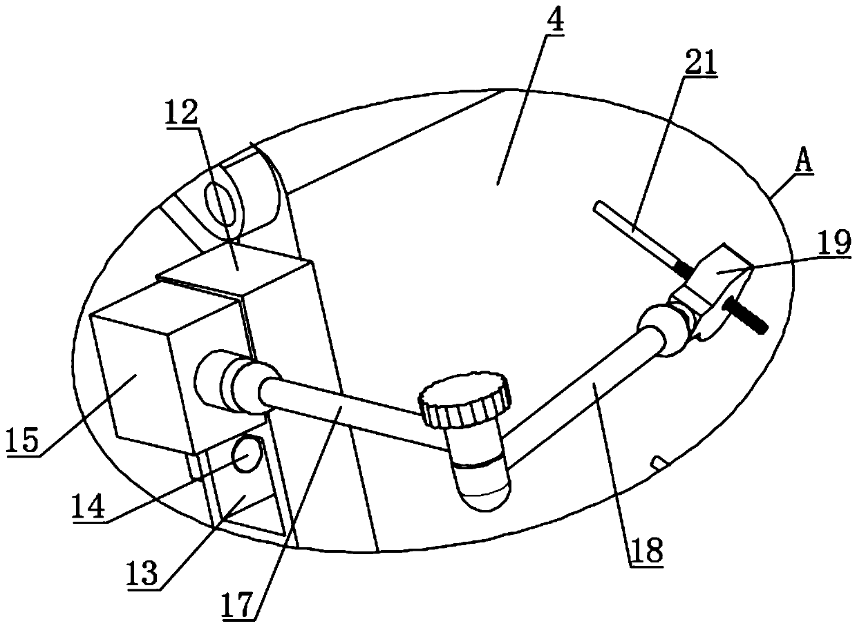
[0029] see Figure 1-14 , the present invention provides a technical solution: a tibial fracture closed reduction multi-directional traction frame, including a base plate 1 with a load-bearing function. When in use, the base plate 1 is fixed on the hospital bed or the operating table through the mounting holes at the four corners. , both ends of the interior of the base plate 1 are provided with chute 2, and the interior of each chute 2 is slidably connected w...


PUM


Abstract

The invention discloses a multi-directional traction frame for closed reduction of tibial fracture. The multi-directional traction frame comprises a bottom plate having a bearing effect, wherein the bottom plate is fixed to an outside device through four-corner mounting holes; sliding chutes are formed in two ends in the bottom plate, and a sliding block is in sliding connection to the inner partof each sliding chute; a first supporting plate and a second supporting plate are rotatably connected to the upper sides of the two sliding blocks, and the upper side of the first supporting plate andthe upper side of the second supporting plate are rotatably connected through a hinge; a plurality of clamping chutes are formed in a fixed rod; a movable block is in movable and clamped connection to the inner part of each clamping chute; and a first connecting rod, a second connecting rod and a holding plate are sequentially and rotatably connected to each movable block, a rotating button is rotatably connected to the inner part of each holding plate, and a clamping rod is in meshed connection to the center of each rotating button. According to the multi-directional traction frame disclosedby the invention, through discretionary rotation of the first connecting rod and the second connecting rod, and through rotating second screw rods, the multi-directional traction frame can be fixed at discretionary position, and besides, the angle of the holding plates can be in universal regulation, so that the clamping rods can be moved leftwards, rightwards, forwards and backwards, and furthereffective traction for multiple fracture sites can be achieved.

Description

technical field [0001] The invention relates to the technical field of reduction and traction, in particular to a multidirectional traction frame for tibial fracture closed reduction. Background technique [0002] Tibial fractures are common clinical fractures. Surgical reduction of tibial fractures is often difficult, especially for multi-segment comminuted fractures. It leads to large trauma, damage to the blood supply of the fracture end, and fracture nonunion. In the past, there were fracture retractors clinically, but they were usually only single-axis longitudinal traction. It is difficult to perfectly reset by relying on axial traction. During treatment, the treatment of tibial fractures is troublesome, which affects the efficiency of surgery and is not conducive to the recovery of patients. Therefore, we propose a multi-directional traction frame for closed reduction of tibial fractures. . Contents of the invention [0003] The purpose of the present invention is...

Claims


Application Information

Patent Timeline
Patent Type & Authority Applications(China)
IPC IPC(8): A61B17/66
Inventor 袁建敏
Owner 袁建敏
Learn More