Eureka AIR delivers breakthrough ideas for toughest innovation challenges, trusted by R&D personnel around the world.

Protocol conversion method and device

A protocol conversion and protocol technology, which is applied in the field of automotive ECU communication, can solve the problems of increasing the material cost and time cost of automotive diagnostic communication, and cannot be used, and achieves the effect of avoiding re-development and design, reducing material costs and improving communication bandwidth.

Active Publication Date: 2019-04-23
LAUNCH TECH CO LTD
View PDF11 Cites 14 Cited by
  • Summary
  • Abstract
  • Description
  • Claims
  • Application Information

AI Technical Summary

Problems solved by technology

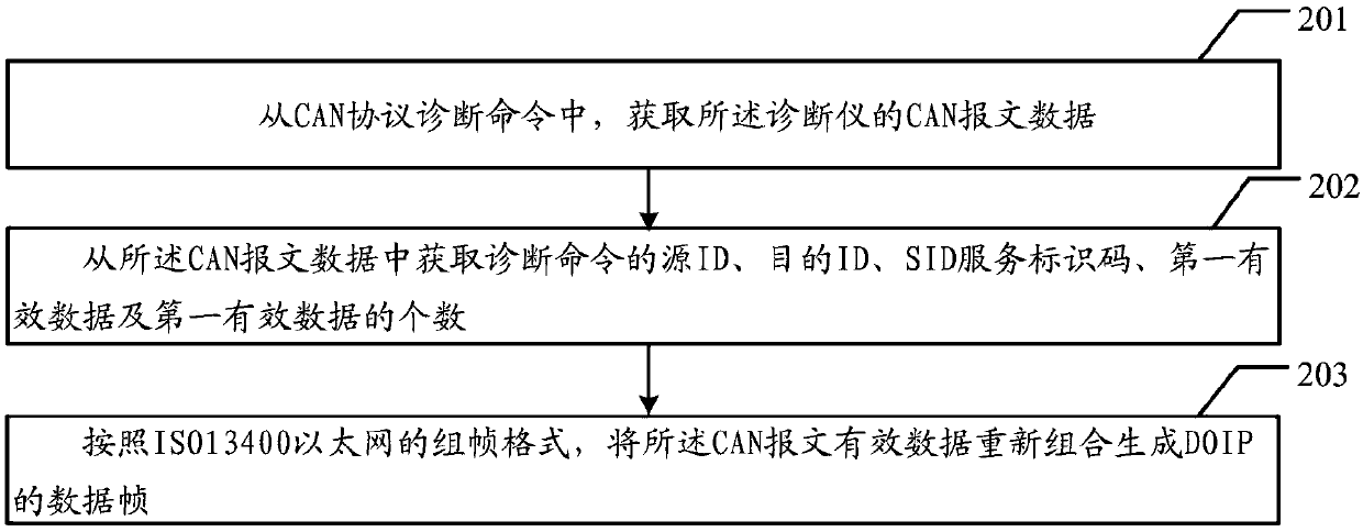
[0002] In the field of automotive diagnostic technology, the current mainstream diagnostic communication protocol is based on the CAN protocol, so most of the diagnostic instrument communication is developed according to the software and hardware standards of the CAN protocol, but as the bandwidth requirements of data communication become higher and higher , the high-speed CAN communication can only reach 500k, and the DOIP Ethernet communication protocol ISO13400 appeared again, and the communication bandwidth of DOIP can reach 100Mb / s, and the software and hardware communication standards of DOIP and CAN are different, which will cause diagnosis The DOIP protocol cannot be used for communication between the instrument and the ECU electronic control unit of the vehicle
[0003] However, if the existing diagnostic instruments want to use the DOIP protocol for communication, they can only develop the diagnostic software developed using the CAN protocol before using the DOIP protocol. At the same time, it is necessary to replace the hardware of the diagnostic instrument to support the DOIP protocol. communication, and this re-development method not only needs to re-open the hardware, but also needs to re-develop and design the software, which will inevitably increase the material cost and time cost of automotive diagnostic communication.

Method used


Image

  • Protocol conversion method and device
  • Protocol conversion method and device
  • Protocol conversion method and device

Examples


Embodiment Construction

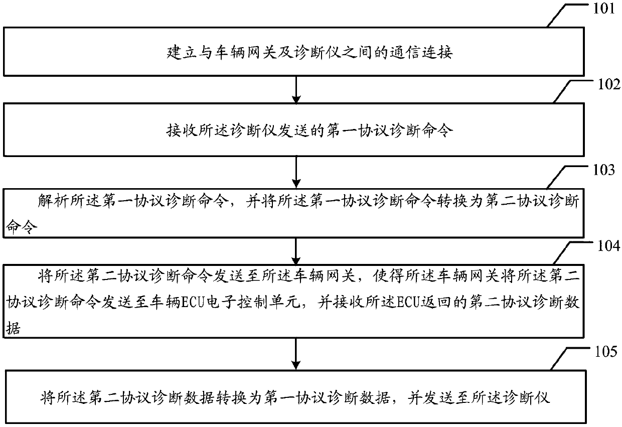
[0050] The embodiment of the present application provides a protocol conversion method and a conversion device, which are used to realize the conversion of the communication protocol between the diagnostic instrument and the vehicle ECU, so as to increase the bandwidth of the vehicle diagnostic communication and reduce the communication cost.

[0051] In order to enable those skilled in the art to better understand the solution of the present application, the technical solution in the embodiment of the application will be clearly and completely described below in conjunction with the accompanying drawings in the embodiment of the application. Obviously, the described embodiment is only It is an embodiment of a part of the application, but not all of the embodiments. Based on the embodiments in this application, all other embodiments obtained by persons of ordinary skill in the art without creative efforts shall fall within the scope of protection of this application.

[0052]T...


PUM


Abstract

The embodiment of the invention discloses a protocol conversion method and device. The protocol conversion method and device are used for converting a communication protocol between a diagnostic instrument and a vehicle electronic control unit (ECU) to increase the bandwidth of vehicle diagnostic communication and meanwhile lower the communication cost. The protocol conversion method comprises thesteps: communication connection with a vehicle gateway and the diagnostic instrument is built; a first protocol diagnostic command sent by the diagnostic instrument is received; the first protocol diagnostic command is analyzed, and the first protocol diagnostic command is converted into a second protocol diagnostic command; the second protocol diagnostic command is sent to the vehicle gateway, and thus the vehicle gateway sends the second protocol diagnostic command to the vehicle ECU and receives second protocol diagnostic data returned by the ECU; and the second protocol diagnostic data are converted into first protocol diagnostic data to be sent to the diagnostic instrument.

Description

technical field [0001] The present application relates to the technical field of automotive ECU communication, in particular to a protocol conversion method and a conversion device. Background technique [0002] In the field of automotive diagnostic technology, the current mainstream diagnostic communication protocol is based on the CAN protocol, so most of the diagnostic instrument communication is developed according to the software and hardware standards of the CAN protocol, but as the bandwidth requirements of data communication become higher and higher , the high-speed CAN communication can only reach 500k, and the DOIP Ethernet communication protocol ISO13400 appeared again, and the communication bandwidth of DOIP can reach 100Mb / s, and the software and hardware communication standards of DOIP and CAN are different, which will cause diagnosis The DOIP protocol cannot be used for communication between the instrument and the ECU electronic control unit of the vehicle. ...

Claims


Application Information

Patent Timeline
IPC IPC(8): G05B23/02
CPCG05B23/0262G05B2219/24065
Inventor 刘均庄文龙刘国柱詹伟程驰
Owner LAUNCH TECH CO LTD
Why Eureka
Eureka Blog
Learn More