
Floor installing structure for compartment

A technology for installing structures and floors, which is applied to superstructures, subassemblies of superstructures, railway car bodies, etc., and can solve problems such as difficult installation, single installation method, and prone to staggered floors

Pending Publication Date: 2019-04-23
JIANGSU TIEKE NEW MATERIAL CO LTD
View PDF0 Cites 4 Cited by
  • Summary
  • Abstract
  • Description
  • Claims
  • Application Information

AI Technical Summary

Problems solved by technology

[0002] Traditionally, the floors used in the carriages of railways, passenger cars and other transport vehicles are directly laid with multi-layer composite materials in the bottom plate of the carriage, and then use the serial connection holes set on the composite materials to pass through the fasteners to make them connect with the bottom of the carriage. The bottom plate is fixed as a whole. The existing installation method of this structure is relatively simple. Because it is only fixed and installed by fasteners, the reliability of its fixation is relatively poor, and multi-layer composite materials are prone to misalignment. The floor is easily damaged and the service life is shortened. Furthermore, the composite material is directly attached to the floor, which makes the comfort not good. In addition, due to the limited space in the compartment, this single installation method also needs to be considered. Composite materials are installed at the same time, and even the floor connectors have to pass directly to the bottom of the car during the installation process, so there are problems such as installation difficulties

Method used

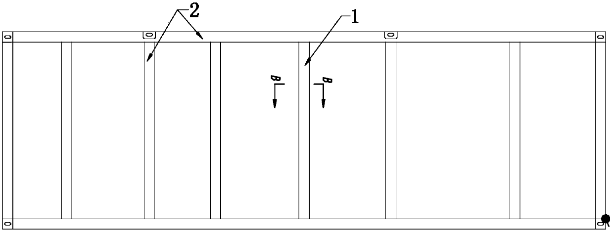
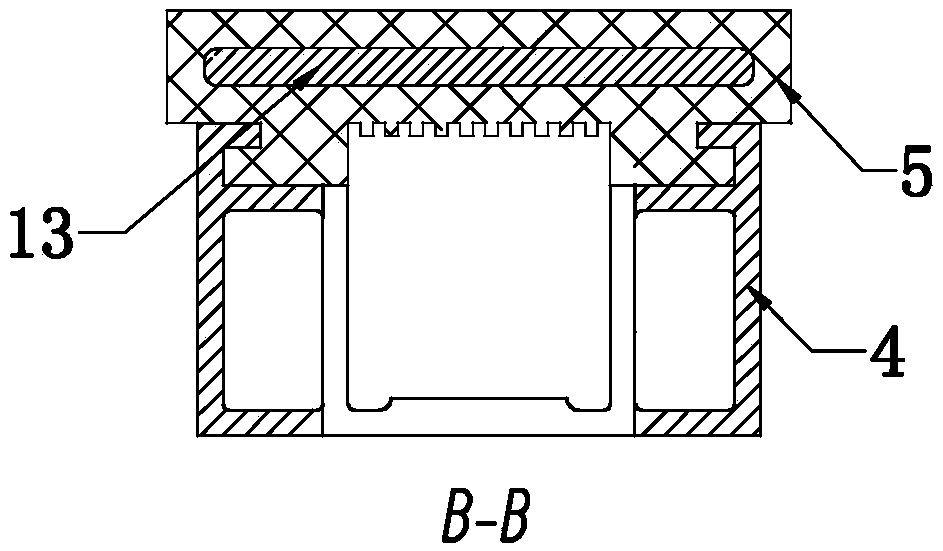

Image

  • Floor installing structure for compartment
  • Floor installing structure for compartment
  • Floor installing structure for compartment

Examples


Embodiment Construction

[0015] The floor mounting structure for the vehicle compartment of the present invention will be further described in detail below in conjunction with the accompanying drawings and specific embodiments.

[0016] As shown in the figure, the car floor installation structure of the present invention includes a support base body 2 formed by interconnecting support frames 1 arranged vertically and horizontally, and a floor structure layer 3 arranged above the support base body 2. As can be seen from the figure, the support frame 1 After being connected with each other, the whole supporting body of a frame structure is formed. The said floor structure layer 3 includes a honeycomb aluminum alloy profile 8, an upper glass fiber layer 9 compounded on the upper layer of the aluminum alloy profile 8, and the surface of the upper glass fiber layer is set The non-woven fabric layer 11 and the lower glass fiber layer 10 that are compositely set on the lower layer of the aluminum alloy profil...


PUM


Abstract

The invention discloses a floor installing structure for a compartment. The floor installing structure for the compartment comprises a support base body formed by mutually connecting vertically and horizontally arranged support frames and a floor structure layer arranged above the support base body; each support frame comprises an aluminum alloy frame and a faceplate installing groove arranged atthe upper part of the aluminum alloy frame; a faceplate made of an elastic material is arranged inside each faceplate installing groove; the floor structure layer passes through each faceplate througha fastener and is fixedly arranged at the upper part of the support base body; a space between the adjacent support frames in the support base body is filled with heat-preserving cotton; and the bottoms of the support frames are fixedly connected with a compartment bottom plate through fasteners. After the above structure is adopted, not only is a comfort level increased through utilizing the faceplates of the elastic material, but also connection reliability is improved; Upper and lower distributed installation is adopted, so that convenience of installation is greatly improved and stabilityand reliability after installation are improved, and the service life of the structure is greatly improved; and in addition, the comfort level is further improved through rational design of the floorstructure layer.

Description

technical field [0001] The invention relates to a component structure in transportation vehicles such as railways and passenger cars, in particular to a floor installation structure for carriages. Background technique [0002] Traditionally, the floors used in the carriages of railways, passenger cars and other transport vehicles are directly laid with multi-layer composite materials in the bottom plate of the carriage, and then use the serial connection holes set on the composite materials to pass through the fasteners to make them connect with the bottom of the carriage. The bottom plate is fixed as a whole. The existing installation method of this structure is relatively simple. Because it is only fixed and installed by fasteners, the reliability of its fixation is relatively poor, and multi-layer composite materials are prone to misalignment. The floor is easily damaged and the service life is shortened. Furthermore, the composite material is directly attached to the flo...

Claims


Application Information

Patent Timeline
IPC IPC(8): B62D25/20B61D17/10B61D17/04
CPCB61D17/043B61D17/10B62D25/20B62D25/2009
Inventor 吕珏丁雷季柱阚鹏生陈永刚谢冰清刘超丁恒凯
Owner JIANGSU TIEKE NEW MATERIAL CO LTD
Learn More