
Rotary valve core structure

A rotary and spool technology, applied in the direction of valve devices, engine components, mechanical equipment, etc., can solve the problems of poor water control effect, large space occupation, knob damage, etc., to achieve comfortable use, small space occupation, and all-round movement Effect

Inactive Publication Date: 2019-04-19
徐少平
View PDF0 Cites 0 Cited by
  • Summary
  • Abstract
  • Description
  • Claims
  • Application Information

AI Technical Summary

Problems solved by technology

Whether it is a hemispherical valve or a gate valve, the spool will age over time, that is, when you turn the knob of the control core handle by hand, the hand will feel very strenuous, and the knob is exposed outside the faucet, taking up a lot of space. In some special In some cases, a person may fall and hit the knob to cause injury
Moreover, the protruding rod of the current spool moves left and right inside the spool, and the water control effect is poor. When the water pressure is low, the water flow is small

Method used


Image

  • Rotary valve core structure

Examples


Embodiment 1

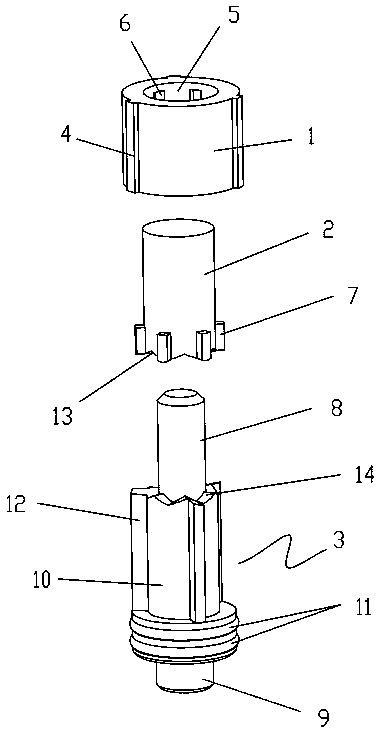
[0010] A rotary valve core structure described in this embodiment 1, such as figure 1 As shown, from top to bottom, it is composed of an upper valve core 1, an inner valve core 2 sleeved in the upper valve core, and a lower valve core 3 partially sleeved and installed with the inner valve core; the outer side of the upper valve core is provided with It is installed in conjunction with the handwheel or handle to drive the upper valve core to the protruding upper clip 4. The upper valve core has an upper valve core cavity 5 that runs through the entire upper valve core along the direction of the central axis. The upper valve core cavity is recessed with Card slot 6; the inner valve core is a columnar structure and the lower part is provided with a middle clip 7 which is fitted with the card slot, and the inner valve core is provided with a unilaterally closed inner valve core cavity from the bottom to the upper direction (not shown in the figure), The inner valve core passes thr...


PUM


Abstract

The invention discloses a rotary valve core structure which is successively composed of an upper valve core, an inner valve core sleeved in the upper valve core and a lower valve core sleeved and mounted to the inner valve core partially from top to bottom. An upper clamping strip mounted matched with a hand wheel or a handle to drive the upper valve core to rotate to be protruded is arranged on the outer side of the upper valve core, the upper valve core along the direction of a center axle is provided with an upper valve core cavity penetrating the whole upper valve core, and a slot is sunken in the upper valve core cavity; the inner valve core is of a columnar structure and a middle clamping strip mounted to the slot in a fit manner is formed on the lower part, the inner valve core is provided with an inner valve core cavity closed at the single side from the upward direction of the bottom, and the inner valve core penetrates the upper valve core cavity and protrudes out of the topof the upper valve core. The lower valve core comprises an upper valve rod inserted into the inner valve core cavity, a lower valve rod connected and mounted to the upper valve rod, a valve rod coversleeved to the periphery of the upper valve rod and mounted and joined to the middle clamping strip and a seal ring sleeved to the connecting position of the upper valve rod and the lower valve rod. The rotary valve core structure is small in occupied space, can move all around, and is good in water control effect, comfortable to use and low in noise.

Description

technical field [0001] The invention relates to the structural field of valve cores, in particular to a rotary valve core structure. Background technique [0002] At present, the valve core on the market is installed in the faucet to control the water flow switch and the flow rate. The valve cores used for faucets include hemispherical valves, gate valves, etc. These two types of valve cores are relatively traditional and the most popular. The half-ball valve is switched through the spherical surface on one side of the valve core and the through hole on the other side to control fluid flow and closed and closed, and the gate valve controls the fluid flow and closing through up and down displacement. Whether it is a hemispherical valve or a gate valve, the valve core will age over time, that is, when the knob of the control core handle is rotated by hand, the hand will feel very hard, and the knob is exposed outside the faucet, occupying a lot of space, in some special In t...

Claims


Application Information

Patent Timeline
Patent Type & Authority Applications(China)
IPC IPC(8): F16K51/00
CPCF16K51/00
Inventor 徐少平
Owner 徐少平
Learn More