Multiple clutch for a motor vehicle, in particular for a hybrid drive of a motor vehicle
What is Al technical title?
Al technical title is built by PatSnap Al team. It summarizes the technical point description of the patent document.
A drive device and hybrid drive technology, applied in the direction of mechanically driven clutches, non-mechanically driven clutches, fluid-driven clutches, etc., can solve the problems of high cost, consumption, and increased manufacturing costs, and achieve reduced manufacturing costs, simplified assembly costs, and manufacturing The effect of cost reduction
Active Publication Date: 2020-08-25
VOLKSWAGEN AG
View PDF9 Cites 0 Cited by
Summary
Abstract
Description
Claims
Application Information
AI Technical Summary
This helps you quickly interpret patents by identifying the three key elements:
Problems solved by technology
Method used
Benefits of technology
Problems solved by technology
On the one hand, the construction and assembly complexity of the known multiple clutches is increased, in particular different discs, in particular differently configured and / or differently dimensioned, have to be produced in part for the first and second separating clutches and also for the third separating clutches optimized friction linings, which also have to be arranged or positioned accordingly in several assembly steps
This results in high cost
Furthermore, the cooling oil system is not yet optimal in the case of already known multiple clutches or multiple clutch systems
Due to the complex spatial arrangement of the corresponding inner and outer plate carriers of the first, second and third separating clutches, partly complex cooling oil channels have to be formed or realized, which in turn increases the manufacturing costs accordingly
Method used
Image
Click on the blue label to locate the original text in one second.
Reading with bidirectional positioning of images and text.
Examples
Embodiment Construction
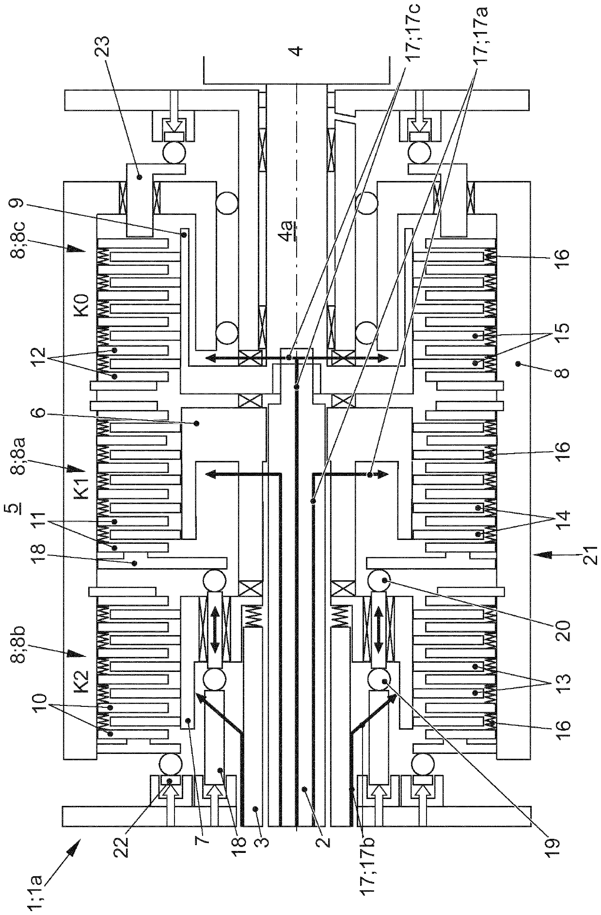
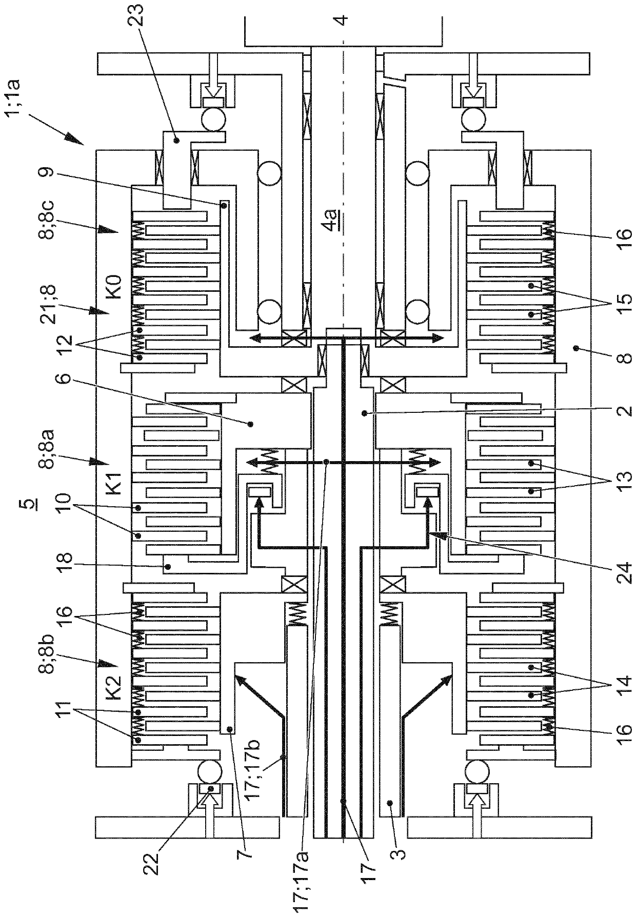
[0023] figure 1 with figure 2 A multiple clutch 1 for a motor vehicle not shown in more detail, in particular for a hybrid drive of a motor vehicle not shown in more detail, is shown at least partially schematically in section. The following implementation basically involves the figure 1 with figure 2 Two implementations are shown in .
[0024] The multiple clutch 1 has at least a first separating clutch K1 , a second separating clutch K2 and a third separating clutch K0 . The first, second and third separating clutches K1 , K2 and K0 are in particular designed as multi-disk clutches or friction clutches.
[0025] The multiple clutch 1 shown here is in particular designed or embodied as a double clutch 1 a with the addition of a so-called “K0 clutch” as a third separating clutch. The multiple clutch 1 shown here or the double clutch 1a shown with an added "K0 clutch" is used in particular to actuate the two transmission input shafts 2 or 3 of a double clutch transmissio...
PUM
Abstract
The invention relates to a multiple clutch (1) for a motor vehicle, particularly for a hybrid drive of a motor vehicle, comprising at least one first, one second and one third separating clutch (K1, K2, KO), the first separating clutch (K1) being provided for coupling a first transmission input shaft (2) to a drive (4 or 5) or uncoupling same therefrom, the second separating clutch (K2) being provided for coupling a second transmission input shaft (3) to a drive (4 or 5) or uncoupling same therefrom, where the first and second separating clutches (K1, K2) are embodied as multiple-plate clutches and comprise an inner plate carrier (6, 7) and an outer plate carrier (8a, 8b), and the third separating clutch (KO) being provided for coupling the outer plate carrier (8a, 8b) of the first and second separating clutches (K1, K2) to a drive (4 or 5) or uncoupling same therefrom, the third separating clutch (KO) being embodied as a multiple-plate clutch, the outer plate carrier (8a, 8b, 8c) of the first, the second and the third separating clutches (K1, K2, KO) being embodied as a common outer plate carrier (8) for receiving, supporting and / or guiding the outer plates (10, 11, 12) of the first, second and third separating clutches (K1, K2, KO), and the actuating piston of the middle separating clutch (K1) has a double bearing.
Description
technical field [0001] The invention relates to a multiple clutch according to the invention for a motor vehicle, in particular for a hybrid drive of a motor vehicle. Background technique [0002] Multiple clutches for motor vehicles, in particular also for hybrid drives of motor vehicles, are already known from a large amount of prior art. [0003] Usually, such multiple clutches have a first, a second and a third separating clutch, which are designed in particular as friction multi-disk clutches. In this case, the first separating clutch is provided for coupling or decoupling the first transmission input shaft to a drive, in particular to an internal combustion engine and / or to an electric motor. In particular in the case of a double clutch transmission, a second separating clutch is then provided, which is provided for coupling or decoupling the second transmission input shaft thus provided with a drive, in particular with an internal combustion engine or with an electri...
Claims
Application Information
Patent Timeline
Application Date:The date an application was filed.
Publication Date:The date a patent or application was officially published.
First Publication Date:The earliest publication date of a patent with the same application number.
Issue Date:Publication date of the patent grant document.
PCT Entry Date:The Entry date of PCT National Phase.
Estimated Expiry Date:The statutory expiry date of a patent right according to the Patent Law, and it is the longest term of protection that the patent right can achieve without the termination of the patent right due to other reasons(Term extension factor has been taken into account ).
Invalid Date:Actual expiry date is based on effective date or publication date of legal transaction data of invalid patent.