Single-camera navigation image-based inspection detector positioning method

A positioning method and patrolling technology, applied in the aerospace field, can solve problems such as inability to complete positioning, lack of texture conditions, and many control points

Active Publication Date: 2019-04-16
LIAONING TECHNICAL UNIVERSITY
View PDF8 Cites 8 Cited by
  • Summary
  • Abstract
  • Description
  • Claims
  • Application Information

AI Technical Summary

Problems solved by technology

[0004] Although the research results of the above-mentioned scholars at home and abroad have achieved good results, the positioning process requires a large number of control points. In addition, the attitude parameters obtained by the inertial measurement unit are required. In the case of lack of texture conditions and a small number of feature points It may not be possible to complete the positioning when one of the navigation cameras fails

Method used


Image

  • Single-camera navigation image-based inspection detector positioning method
  • Single-camera navigation image-based inspection detector positioning method
  • Single-camera navigation image-based inspection detector positioning method

Examples


Embodiment Construction

[0063] The specific implementation manners of the present invention will be further described in detail below in conjunction with the accompanying drawings and embodiments. The following examples are used to illustrate the present invention, but are not intended to limit the scope of the present invention.

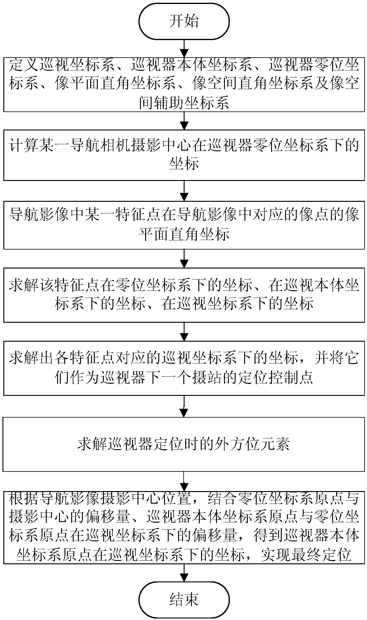
[0064] A positioning method for patrol detectors based on single-camera navigation images, such as figure 1 shown, including the following steps:

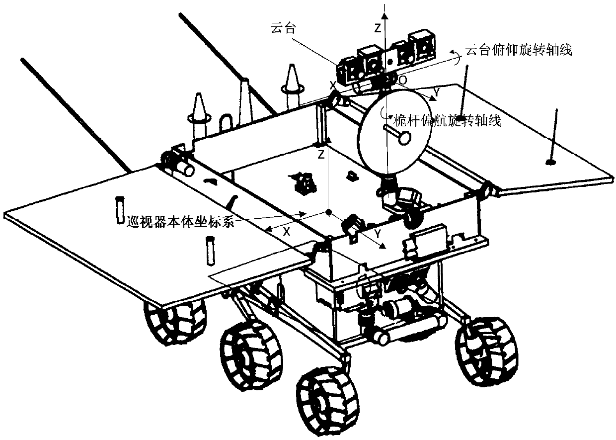
[0065] Step 1. Define the patrol coordinate system, the patrol body coordinate system, the patrol zero coordinate system, the image plane Cartesian coordinate system, the image space Cartesian coordinate system and the image space auxiliary coordinate system;

[0066] The inspection coordinate system: the camera station where the inspection mission is about to be carried out after the patrol and the lander are separated is used as a reference, that is, the patrol body coordinate system at the position of the first camera stati...


PUM


Abstract

The invention provides a single-camera navigation image-based inspection detector positioning method and belongs to the technical field of aerospace. According to the method, a plurality of coordinatesystems are defined; the coordinates of a certain navigation camera photography center in an inspector zero-position coordinate system and the image plane rectangular coordinates of an image point ina navigation image which is corresponding to a feature point in the navigation image are obtained, so that the coordinates of the point in the zero-position coordinate system, a body coordinate system and an inspection coordinate system are obtained; and the coordinates of the origin of the inspector body coordinate system under the inspection coordinate system are obtained according to the deviation quantity of the origin of the zero-position coordinate system and the photography center, and the deviation quantity of the origin of the body coordinate system and the origin of the zero-position coordinate system under the inspection coordinate system, so that final positioning is realized. With the single-camera navigation image-based inspection detector positioning method provided by theinvention adopted, high-precision positioning can be realized with two control points even when one navigation camera fails, and therefore, the method depends on fewer initial conditions.

Description

technical field [0001] The invention relates to the field of aerospace technology, in particular to a positioning method for a patrol detector based on a single-camera navigation image. Background technique [0002] The high-precision navigation and positioning of patrol detectors is one of the key technologies for carrying out deep space scientific investigation missions. High-precision positioning can ensure the safety of the patrol, and high-precision attitude information can ensure that it maintains a good pointing angle with the ground control system. Existing high-precision positioning methods for patrol detectors mainly include positioning methods based on odometers and IMUs, and positioning methods based on photogrammetry. Localization methods based on odometry and IMU have accumulated errors, therefore, photogrammetry-based methods must be used to make necessary corrections. In areas rich in control points, existing photogrammetry positioning methods such as the b...

Claims


Application Information

Patent Timeline
IPC IPC(8): G01C21/00
CPCG01C21/00
Inventor 徐辛超徐宗秋郑涛刘明跃李旭佳
Owner LIAONING TECHNICAL UNIVERSITY
Why Eureka
Try Eureka