
Position control part and plunger

A technology for controlling components and plungers, which is applied to components of pumping devices for elastic fluids, variable displacement pump components, wellbore/well components, etc. question

Pending Publication Date: 2019-04-16
成都百胜野牛科技有限公司
View PDF0 Cites 0 Cited by
  • Summary
  • Abstract
  • Description
  • Claims
  • Application Information

AI Technical Summary

Problems solved by technology

However, oil and gas wells cannot produce in the well shut-in state, which greatly reduces the production efficiency of oil and gas wells

Method used


Image

  • Position control part and plunger
  • Position control part and plunger
  • Position control part and plunger

Examples


Embodiment 1

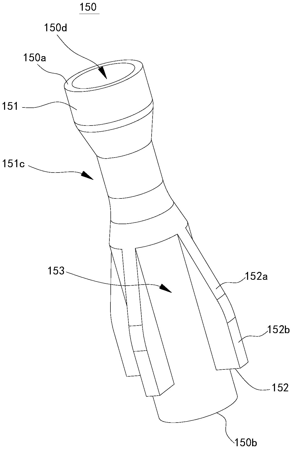
[0032] Please refer to figure 1 and figure 2 , this embodiment provides a plunger 010. The plunger 010 includes a core tube 110 , a packing piece 120 , a first elastic reset member 130 , a linkage member 140 , a position control component 150 , a driving mechanism 160 , a second elastic reset member 170 , an upper plug 180 and a lower plug 190 .

[0033]The core pipe 110 is a circular tube, and the upper plug 180 and the lower plug 190 are also circular tubes. The upper plug 180 and the lower plug 190 are screwed to the upper and lower ends of the core tube 110 respectively. A plurality of upper flow holes 180 a communicating with the inner space of the core tube 110 are opened on the periphery of the upper plug 180 . The periphery of the lower plug 190 defines a plurality of lower through holes 190a communicating with the inner space of the core tube 110 . Fluid can enter the core tube 110 through the lower through hole 190a, and flow out of the core tube 110 through the...


PUM


Abstract

The invention relates to the technical field of natural gas and oil exploitation, and discloses a position control part and a plunger. When the plunger provided by the embodiment of the invention needs to move downwards, the position control part moves from the expanded position to the retracted position, so that the sealing spacers retract inwards to the position close to the inner position in radial direction, at this moment the maximum outer diameter of the plunger is smaller than the inner diameter of an oil-gas well shaft, friction between the packers and the inner wall of the well shaftis eliminated, a space for fluid to pass through is formed between the plunger and the inner wall of the well shaft, so that downward resistance of the plunger is greatly reduced. In addition, the position control part controls the radial positions of the sealing spacers through position control surfaces on fins, so that flow spaces allowing fluid to pass through can be formed between adjacent fins. When the plunger allows the fluid to pass through a core tube when moving downwards, flow area of the core tube can be increased due to the existence of the flow spaces, so that downward resistanceof the plunger is reduced to a greater extent, and the plunger can move downwards to the bottom of the well more rapidly.

Description

technical field [0001] The invention relates to the technical field of natural gas and oil exploitation, in particular to a position control component and a plunger. Background technique [0002] In oil and gas wells, the problem is to drain the accumulated fluid at the bottom of the well, and a plunger is usually used. The plunger has a plurality of packing sheets arranged in the circumferential direction, and these packing sheets are tightly attached to the inner wall of the well of the oil and gas well under the action of the elastic member to form a seal. In the open well state, the plunger goes up and lifts the accumulated fluid above it to be discharged out of the oil and gas well. In the shut-in state, the plunger goes down to the bottom of the well. Reciprocating in this way, the continuous lifting of the bottom fluid is realized. A big problem with the traditional plunger is that under the action of the friction between the packing plate and the inner wall of the...

Claims


Application Information

Patent Timeline
Patent Type & Authority Applications(China)
IPC IPC(8): F04B47/12F04B53/02F04B53/14E21B43/00
CPCE21B43/00F04B47/12F04B53/02F04B53/143
Inventor 刘书豪唐勇陈俊宏苏诗策刘树飞
Owner 成都百胜野牛科技有限公司
Learn More