
Rocket engine thrust chamber testing method

A rocket engine and test method technology, applied in the field of rocket engine thrust chamber test, can solve the problem of high cost, achieve the effects of reducing test cost, shortening test period, and avoiding damage

Active Publication Date: 2019-04-16
BEIJING XINGJI RONGYAO SPACE TECH CO LTD
View PDF5 Cites 2 Cited by
  • Summary
  • Abstract
  • Description
  • Claims
  • Application Information

AI Technical Summary

Problems solved by technology

[0005] The main purpose of the present invention is to provide a rocket engine thrust chamber test method, to solve the problem of high cost in the rocket engine thrust chamber test in the prior art while realizing the test in different working condition ranges where the rocket engine is located

Method used


Image

  • Rocket engine thrust chamber testing method
  • Rocket engine thrust chamber testing method

Examples


Embodiment Construction

[0030] The technical solutions of the present invention will be clearly and completely described below in conjunction with the accompanying drawings. Apparently, the described embodiments are some of the embodiments of the present invention, but not all of them. Based on the embodiments of the present invention, all other embodiments obtained by persons of ordinary skill in the art without making creative efforts belong to the protection scope of the present invention.

[0031] In the description of the present invention, it should be noted that the terms "center", "upper", "lower", "left", "right", "vertical", "horizontal", "inner", "outer" etc. The indicated orientation or positional relationship is based on the orientation or positional relationship shown in the drawings, and is only for the convenience of describing the present invention and simplifying the description, rather than indicating or implying that the referred device or element must have a specific orientation, ...


PUM


Abstract

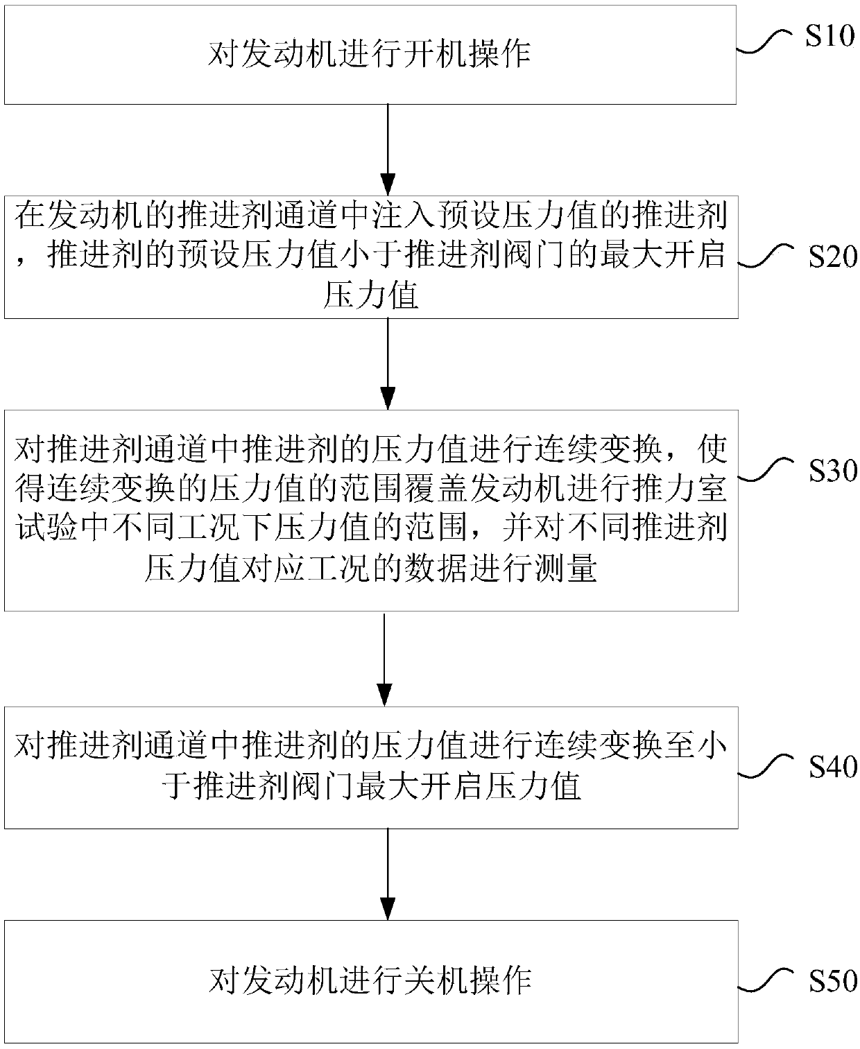
The invention relates to the technical field of rockets, in particular to a rocket engine thrust chamber testing method. The method comprises the steps that starting operation is conducted on an engine; a propellant channel of the engine is filled with a propellant with an initial pressure value, and the initial pressure value of the propellant is smaller than a maximum opening pressure value of apropellant valve; continuous transformation is conducted on the pressure value of the propellant in the propellant channel, the range of pressure values of the engine under different working conditions in a thrust chamber test is covered with the continuous transformation pressure value range, and data under the working conditions corresponding to the different propellant pressure values are measured; and continuous transformation is conducted on the pressure value of the propellant in the propellant channel till the pressure value of the propellant is smaller than the maximum opening pressure value of the propellant valve. Therefore, testing in different working condition ranges of the engine can be achieved by adopting a conventional propellant valve, a high-pressure valve matched witha high-pressure propellant scheme does not need to be separately designed or purchased, the testing cost is reduced, and the testing period is shortened.

Description

technical field [0001] The invention relates to the technical field of rockets, in particular to a method for testing a thrust chamber of a rocket engine. Background technique [0002] At present, in the actual work of a high-thrust liquid rocket engine, propellants such as fuel and oxidant will pass through the pipeline, pass through the valve that controls the on-off of the pipeline, and then go to the thrust chamber, and then ignite through the igniter, and the gas generated by the combustion of the oxidizer and fuel will be released in the thrust chamber. It is sprayed out to realize the propulsion function of the rocket engine. In the actual work of the liquid rocket engine, when the rocket engine supplies propellant, it will use a pump pressure supply system to supply propellant with a certain pressure, so that the liquid rocket engine can be in a better working condition and obtain better propulsion. [0003] In the prior art, during the development of different type...

Claims


Application Information

Patent Timeline
IPC IPC(8): F02K9/96
CPCF02K9/96
Inventor 不公告发明人
Owner BEIJING XINGJI RONGYAO SPACE TECH CO LTD
Learn More