Direct-insert rapid positioning reducer connecting device for metal pipe

A technology of variable diameter connection and metal pipe, which is applied in the direction of sealing surface connection, pipe/pipe joint/pipe fitting, passing components, etc. It can solve the problems of easy loose nuts, troubles, and gaps, etc., and achieve the effect of convenient and fast installation

Active Publication Date: 2019-04-12
佛山德源电子实业有限公司
View PDF8 Cites 0 Cited by
  • Summary
  • Abstract
  • Description
  • Claims
  • Application Information

AI Technical Summary

Problems solved by technology

[0006] Aiming at the deficiencies in the prior art, the purpose of the present invention is to provide an in-line fast positioning metal pipe variable diameter connection device to solve the problem of troublesome alignment and positioning, easy misalignment, need for repositioning and calibration, waste of time, or It will cause an angle between the pipe and the connecting device, and there will be a gap, which will cause the fluid or gas in the pipe to leak during use, causing unnecessary losses and hazards. The nuts used to tighten and fix are easy to loosen. The connection between the devices becomes unstable and tight, resulting in water and air leakage, poor battery life, frequent maintenance, domestic sewage and other gases with a pungent smell will flow back up through the pipes and the passages inside the connecting devices Outlets or other outlets that affect daily life

Method used


Image

  • Direct-insert rapid positioning reducer connecting device for metal pipe
  • Direct-insert rapid positioning reducer connecting device for metal pipe
  • Direct-insert rapid positioning reducer connecting device for metal pipe

Examples


Embodiment Construction

[0029] In order to make the technical means, creative features, goals and effects achieved by the present invention easy to understand, the present invention will be further described below in conjunction with specific embodiments.

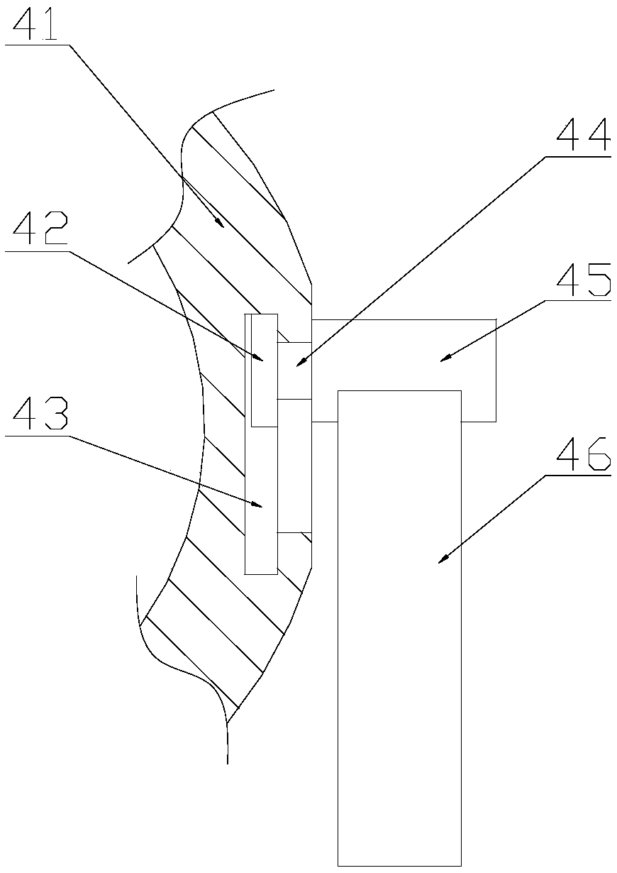
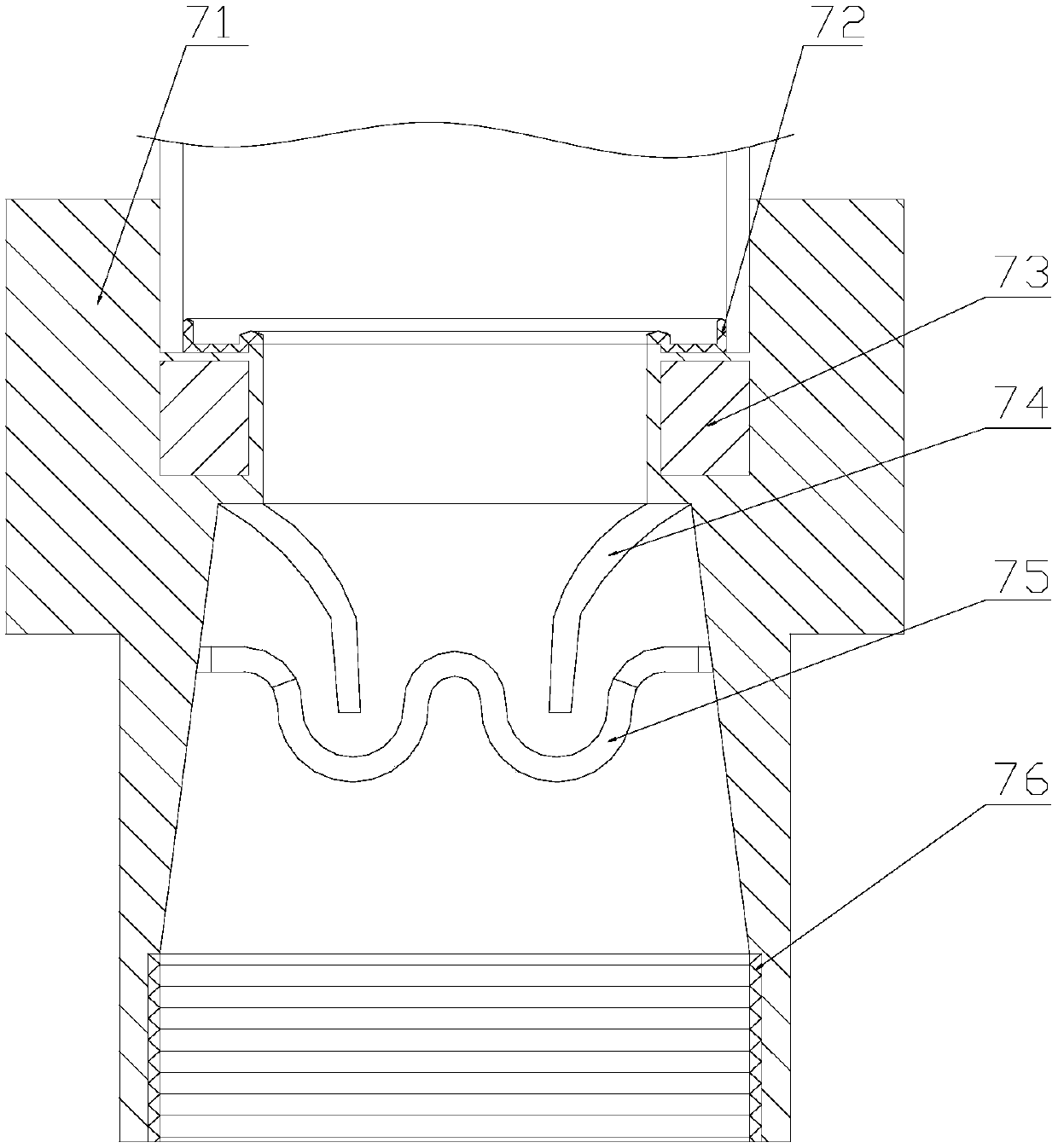
[0030] see figure 1 , the fixed pressing block 1, the small end 2, the anti-slip clamping block 3, the tightening nut 4, the male engraved scale 5, the large end 6, the connecting sleeve main body 7, the anti-slip bump 8, it is characterized in that: the fixed The side of the pressing block 1 close to the big end 6 and the side of the connecting sleeve main body 7 close to the small end 2 are integral structures, and the small end 2 and the fixed pressing block 1 are located on the same axis and run through the connecting sleeve main body 7. The anti-slip clamping block 3 and the small end 2 are located on the same axis and the outer side is welded to the inner side of the fixed pressing block 1. The tightening nut 4 is in clearance fit with the ...


PUM


Abstract

The invention discloses a direct-insert rapid positioning reducer connecting device for a metal pipe. The connecting device structurally comprises fixed hold-down blocks, a small end, antiskid clamping blocks, a tightening nut, a relief scale, a large end, a connecting sleeve main body and antiskid lugs; and one side, near the large end, of each fixed hold-down block and one side, near the small end, of the connecting sleeve main body are of an integral structure. Compared with the prior art, the connecting device has the characteristics that the pipe is rapidly positioned through an annular magnet, so that the efficiency and the accuracy of pipe installation are increased, and time is saved; a seal ring and the outer edge of the pipeline are nested, and attaching pressure is boosted by amagnetic force, so that the condition that liquid or gas in the pipe leaks to cause unnecessary losses and damage during use is avoided; a snap-gauge is stuck into and the tightening nut is screwed into a reverse groove of the relief scale, and the tightening nut is fixed so as to avoid the phenomenon that the tightening nut gets loosened due to the fact that rapid flow rushes to the pipe to makethe pipe continuously generate vibration; and a little gas having a pungent odor is isolated by utilizing accumulated water tank, so that the phenomenon that the gas returns back to a discharge hole or other exits to influence living is avoided.

Description

technical field [0001] The invention belongs to the field of connection devices, and in particular relates to an in-line fast positioning metal pipe variable diameter connection device. Background technique [0002] The variable diameter is a connection device, commonly known as the size head, which is relatively open at the large end and relatively contracted at the small end. It is used for the connection between valves and pipes, or when the nominal diameters of pipes and pipes are inconsistent. It is widely used in sewage treatment, pharmaceuticals, dairy products, food, beer, beverages and other fields. What the prior art considers insufficiently is: [0003] 1. The connecting device in the prior art generally uses threads to connect with the other two pipes. It is troublesome when aligning and positioning, and it is easy to be misplaced. When the positioning is misplaced, it will make it difficult to connect the connecting device and the pipes through threads. It is n...

Claims


Application Information

Patent Timeline
IPC IPC(8): F16L19/00
CPCF16L19/00
Inventor 钱丽玉
Owner 佛山德源电子实业有限公司
Why Eureka
Try Eureka