
Fixtures for Interventional Medical Devices

A technology of medical devices and fixing devices, which is applied in the field of medical devices, can solve the problems of complications and rejection reactions caused by patients, tissue bleeding caused by base friction, blood leakage at the position where pull wires pass through, and so on, so as to reduce the occurrence of complications and rejection reactions Chance, Avoid Bleeding, Smaller Structure Effects

Active Publication Date: 2022-04-05
LIFETECH SCI (SHENZHEN) CO LTD
View PDF5 Cites 0 Cited by
  • Summary
  • Abstract
  • Description
  • Claims
  • Application Information

AI Technical Summary

Problems solved by technology

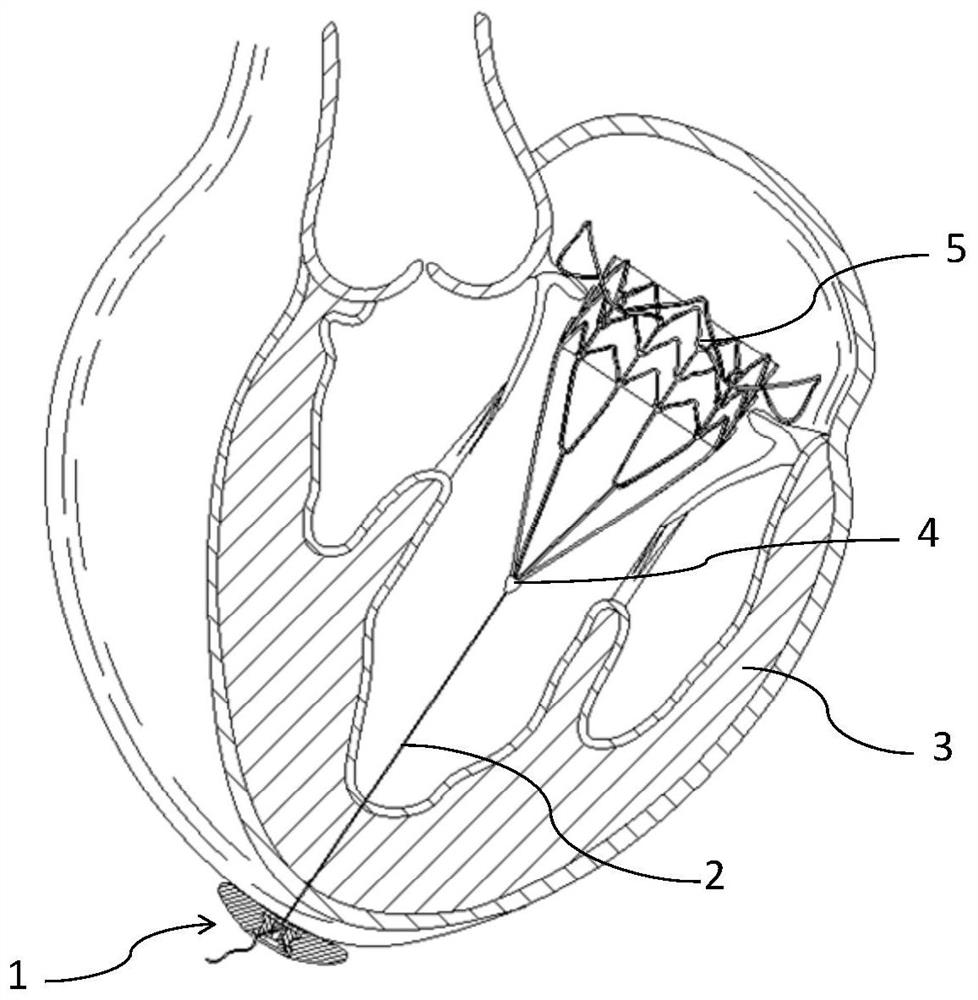
[0004] However, the fixation devices in the prior art are large in size and complex in structure, which are easy to cause complications and rejection reactions to patients; because the diameter of the needle-type stopper is very small (in order to effectively pass through the pull wire), and it is used for a long time, it is easy to cause The failure of the limit of the pull wire will pose a threat to the life safety of the patient; in addition, during the fixation process, it is necessary to use the needle-shaped limit rod to pierce the pull wire. Due to the small diameter of the pull wire, if the passing position is not appropriate, it is easy to cause the pull wire to break. It poses a threat to the life safety of the patient; moreover, due to its large size, it is bound to have a large contact area with the tissue during fixation. The base of the fixation device is a hard object, which will warp at the apex of the heart, resulting in blood leakage from the position where the pull wire passes And base friction tissue produces bleeding and other conditions

Method used


Image

  • Fixtures for Interventional Medical Devices
  • Fixtures for Interventional Medical Devices
  • Fixtures for Interventional Medical Devices

Examples


no. 1 example

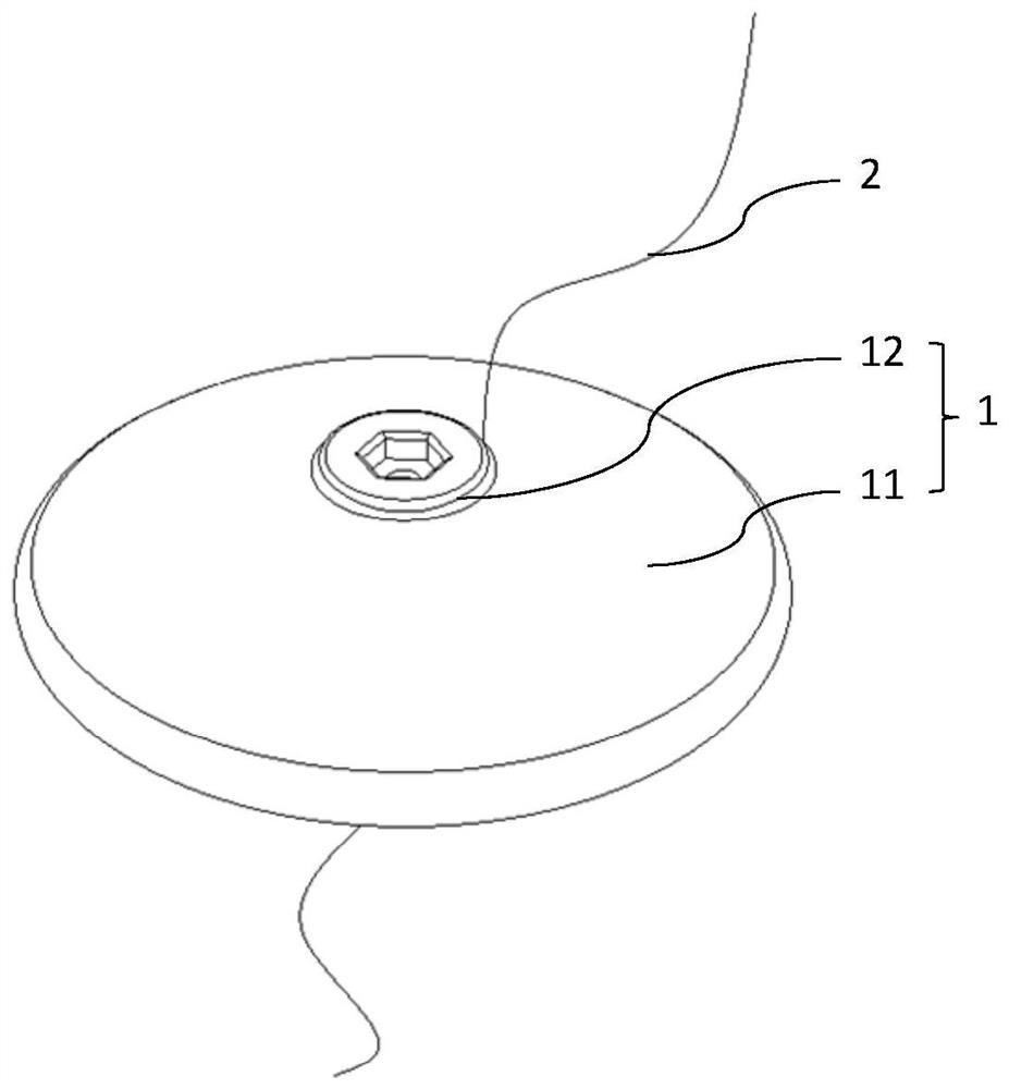
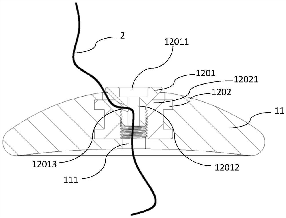
[0042] Please refer to Figure 1 to Figure 7 and Figure 25 The fixing device for interventional medical devices provided by the first embodiment of the present invention includes a fixing assembly 12 and a gasket 11 provided with a through hole 111, the gasket 11 is attached to the outer surface of the organ 3, and the fixing assembly 12 can be It is connected to the gasket 11 in a detachable manner, and the inside of the fixing component 12 is provided with a cable channel. The cable 2 of the interventional medical device 5 passes through the interior of the organ 3 and passes through the through hole 111 and the cable channel in turn. When the cable channel is opened The length of the stay wire 2 can be adjusted, and the length of the stay wire 2 is fixed when the stay wire channel is closed. Specifically, the gasket 11 is a sheet-like structure with two widths, through-holes 111 are provided through the two widths, one of the widths is attached to the outer surface of the...

no. 2 example

[0063] Please refer to figure 1 , Figure 8 to Figure 12 with Figure 25 The fixing device for interventional medical devices provided by the second embodiment of the present invention includes a gasket 11 with a through hole 111 and a fixing assembly 12, the gasket 11 is attached to the outer surface of the organ 3, and the fixing assembly 12 can be It is connected to the spacer 11 in a detachable manner, and the inside of the fixing component 12 is provided with a pull wire channel. The pull wire 2 used to pull the interventional medical device 5 passes through the inside of the organ 3 and passes through the through hole 111 and the pull wire channel in turn. The pull wire When the channel is opened or closed, the length of the stay wire 2 is adjustable or fixed.

[0064] Differences between the second embodiment and the first embodiment will be described below, and the same or similar points between the second embodiment and the first embodiment will not be repeated here...

no. 3 example

[0075] Please refer to figure 1 , Figure 13 to Figure 18 with Figure 25 The fixing device for interventional medical devices provided by the third embodiment of the present invention includes a gasket 11 with a through hole 111 and a fixing assembly 12, the gasket 11 is attached to the outer surface of the organ 3, and the fixing assembly 12 can be It is connected to the gasket 11 in a detachable manner, and the inside of the fixing component 12 is provided with a pull wire channel. The pull wire 2 of the interventional medical device 5 passes through the interior of the organ 3 and passes through the through hole 111 and the pull wire channel in turn. The pull wire channel is opened or When closed, the length of the stay wire 2 is adjustable or fixed.

[0076] Differences between the third embodiment and the first embodiment will be described below, and the same or similar points between the third embodiment and the first embodiment will not be repeated here.

[0077] Sp...


PUM


Abstract

The invention discloses a fixing device for an interventional medical device, which comprises a fixing component and a gasket provided with a through hole, the gasket is used to fit on the outer surface of an organ, and the fixing component is connected to the gasket in a detachable manner , the inside of the fixed component is provided with a pull wire channel, the pull wire of the interventional medical device passes through the interior of the organ and passes through the through hole and the pull wire channel in turn, the length of the pull wire can be adjusted when the pull wire channel is opened, and the length of the pull wire when the pull wire channel is closed The length is fixed. The above-mentioned fixing device is small in size and simple in structure. At the same time, it is easy to operate and can quickly complete the fixing and adjustment of the stay wire. In addition, the contact area with the stay wire is large, which can avoid damage to the stay wire or failure of fixation, and ensure the safety of the patient. The overall structure of the patient is small and compact, and it fits well with the organs, avoiding the occurrence of blood leakage at the position where the pull wire passes through and bleeding caused by the friction tissue of the base, thereby reducing the chance of complications and rejection reactions.

Description

technical field [0001] The invention relates to the technical field of medical instruments, in particular to a fixing device for interventional medical instruments. Background technique [0002] With the continuous advancement of science and technology, percutaneous interventional technology has been widely used in the field of disease treatment. Percutaneous interventional technology is to intervene in the human body through catheters. Plugs and blood vessel filters, etc.) or drugs are placed in the lesion position of the human body, so as to achieve the treatment of the disease. [0003] In order to ensure the best working condition of some interventional medical devices, their working position and posture need to be limited. Therefore, in order to ensure the working position and posture of interventional medical devices, it is necessary to set up a fixing device outside the organ, so as to provide The machine provides good traction. For example, when treating the diseas...

Claims


Application Information

Patent Timeline
Patent Type & Authority Patents(China)
IPC IPC(8): A61B17/04A61F2/24
CPCA61F2/95A61F2002/9511
Inventor 姚斌
Owner LIFETECH SCI (SHENZHEN) CO LTD
Learn More