
Tool, and test apparatus and method

A jig and display technology, applied in nonlinear optics, instruments, optics, etc., can solve the problems of inability to test the lighting of the display, and the fixture of the lighting of the display is not universal, so as to achieve universality and reduce production. cost effect

Active Publication Date: 2019-04-05
SHANGHAI MICRO ELECTRONICS EQUIP (GRP) CO LTD
View PDF5 Cites 6 Cited by
  • Summary
  • Abstract
  • Description
  • Claims
  • Application Information

AI Technical Summary

Problems solved by technology

[0004] The purpose of the present invention is to provide a fixture, testing device and method to solve the problems that the existing fixtures for lighting display screens are not universal and cannot perform lighting tests on display screens of different sizes.

Method used


Image

  • Tool, and test apparatus and method
  • Tool, and test apparatus and method
  • Tool, and test apparatus and method

Examples


Embodiment 1

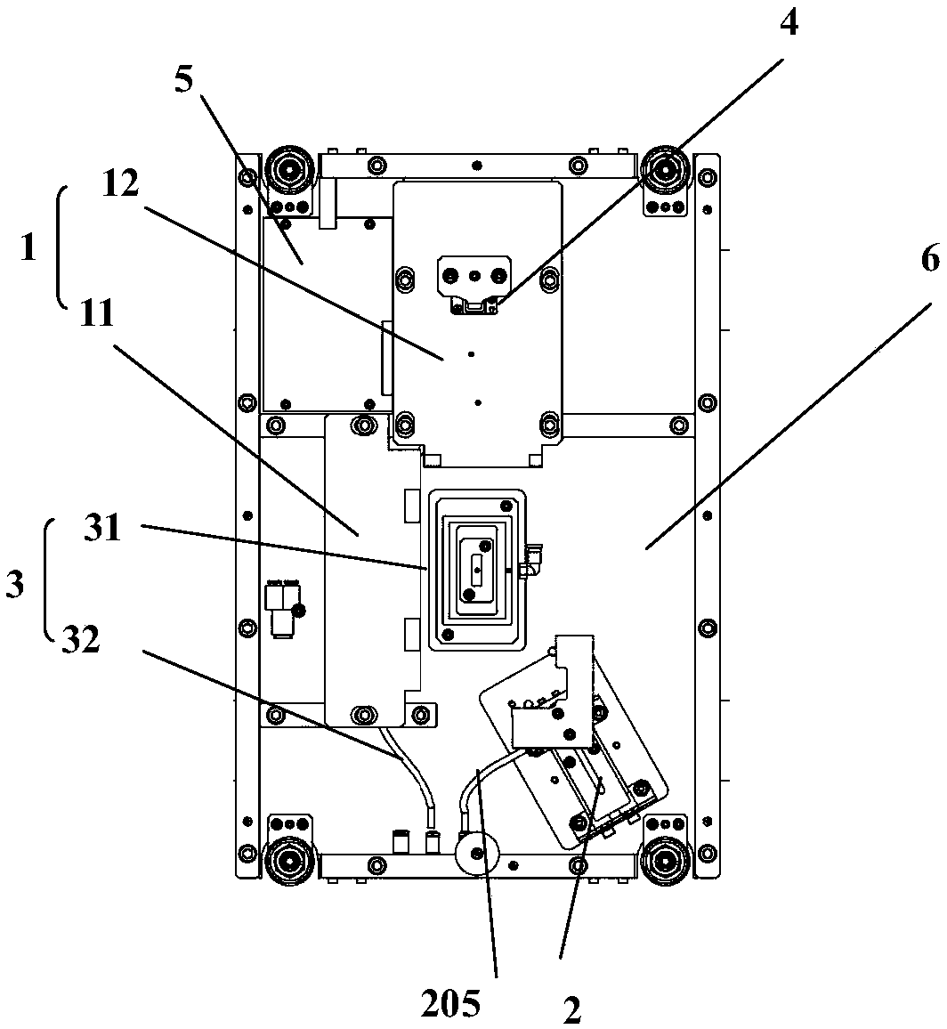
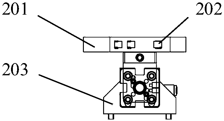
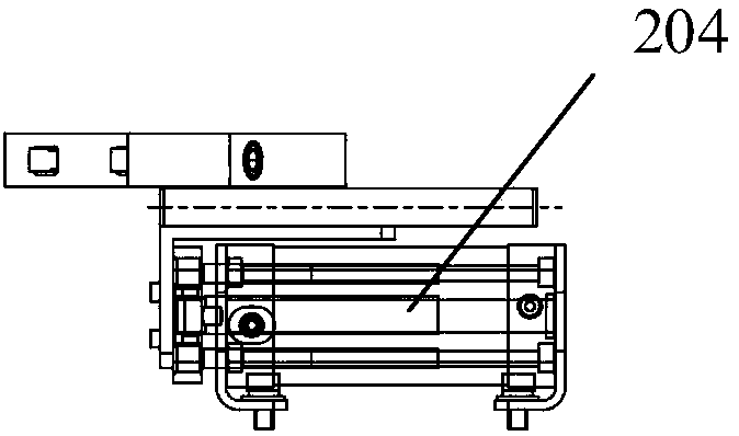
[0048] refer to figure 1 , which is a schematic diagram of the fixture provided in the embodiment, such as figure 1As shown, the jig includes a base 6 and a positioning reference unit 1, a clamping unit 2, an adsorption unit 3, a crimping unit 4 and a lighting signal board 5 arranged on the base 6; the clamping unit 2 and the The positioning reference unit 1 moves relatively and makes the display screen clamped between the clamping unit 2 and the positioning reference unit 1; the adsorption unit 3 is used to absorb the display screen; the crimping unit 4 Realize the signal connection between the lighting signal board 5 and the FPC interface of the display screen. The jig provided by the present invention can clamp the display screen between the positioning reference unit 1 and the clamping unit through the relative movement of the clamping unit 2 and the positioning reference unit 1, because the clamping unit 2 can It moves on the base, so it can clamp display screens of dif...

Embodiment 2

[0059] Such as Figure 8 As shown, in this embodiment, the jig includes a base and a positioning reference unit, a clamping unit, an adsorption unit 3, a crimping unit 4 and a lighting signal board arranged on the base; the clamping unit can be placed on the Move on the base and make the display screen be clamped between the clamping unit and the positioning reference unit; the adsorption unit 3 is used to absorb the display screen; the crimping unit 4 realizes the lighting The signal board is connected to the signal of the FPC interface of the display screen. The difference between this embodiment and Embodiment 1 is that both the positioning reference unit and the clamping unit can move axially, and the stroke of the positioning reference mechanism is locked according to the position and size of the display screen. Within the stroke range, the drive positioning reference unit and the clamping unit move synchronously and oppositely to push the display screen, specifically as...


PUM


Abstract

The invention provides a tool, and a test apparatus and method. The tool comprises a base, a positioning reference unit, a clamping unit, an absorption unit, a crimping unit, and a lighting signal board arranged on the base. The clamping unit and the positioning reference unit can move relative to the other, such that a display screen is clamped between the clamping unit and the positioning reference unit. The absorption unit is used for absorbing the display screen after the display screen is positioned. The crimping unit realizes a signal connection between the lighting signal board and a FPC interface of the display screen. The clamping unit moves on the base, so as to clamp display screens of different sizes between the positioning reference unit and the clamping unit, thus realizing the universality of the tool and reducing the production cost thereof.

Description

technical field [0001] The invention relates to the technical field of screen manufacturing, in particular to a fixture, a testing device and a method. Background technique [0002] At present, liquid crystal displays are widely used in various electronic products such as mobile phones, TVs, and computers. The relative position and angle of the backlight source make the angle and uniformity of the light emitted by the backlight source meet the control requirements. [0003] However, due to the various sizes and shapes of liquid crystal display screens, the existing backlight lighting fixtures need to be specially designed for the product models of liquid crystal display devices, which are not universal, resulting in waste of resources and increasing the production of liquid crystal display screens. cost. Contents of the invention [0004] The object of the present invention is to provide a fixture, testing device and method to solve the problems that the existing fixture...

Claims


Application Information

Patent Timeline
Patent Type & Authority Applications(China)
IPC IPC(8): G02F1/13
CPCG02F1/1309G02F1/13
Inventor 徐健王璟朱岳彬刘剑李永维魏柏林彭之威周畅
Owner SHANGHAI MICRO ELECTRONICS EQUIP (GRP) CO LTD
Learn More