Standard resistance system for correction of grounding conduction resistance tester

A technology of resistance tester and standard resistance, which is applied in the direction of instruments, measuring devices, measuring electrical variables, etc., can solve the problems of inability to calibrate the ground continuity tester, great influence on resistance stability, and low calibration efficiency, etc., and achieve reduction The effect of manual operation and mechanical structure, high precision and reliability, and high accuracy level

Pending Publication Date: 2019-04-05
HENAN PROVINCE INST OF METROLOGY
View PDF0 Cites 2 Cited by
  • Summary
  • Abstract
  • Description
  • Claims
  • Application Information

AI Technical Summary

Problems solved by technology

But this kind of standard device has obvious disadvantages. First, it must be verified by four-terminal connection method.
2. Due to the influence of zero point drift, gain drift, nonlinearity, etc., the stability of the resistance value is greatly affected
3. Due to the limitation of the principle, the ground continuity tester with only two terminals cannot be calibrated
The above three standard resistors have defects such as low degree of automation, cumbersome operation, labor and time-consuming, and low calibration efficiency.

Method used


Image

  • Standard resistance system for correction of grounding conduction resistance tester
  • Standard resistance system for correction of grounding conduction resistance tester
  • Standard resistance system for correction of grounding conduction resistance tester

Examples


Embodiment 1

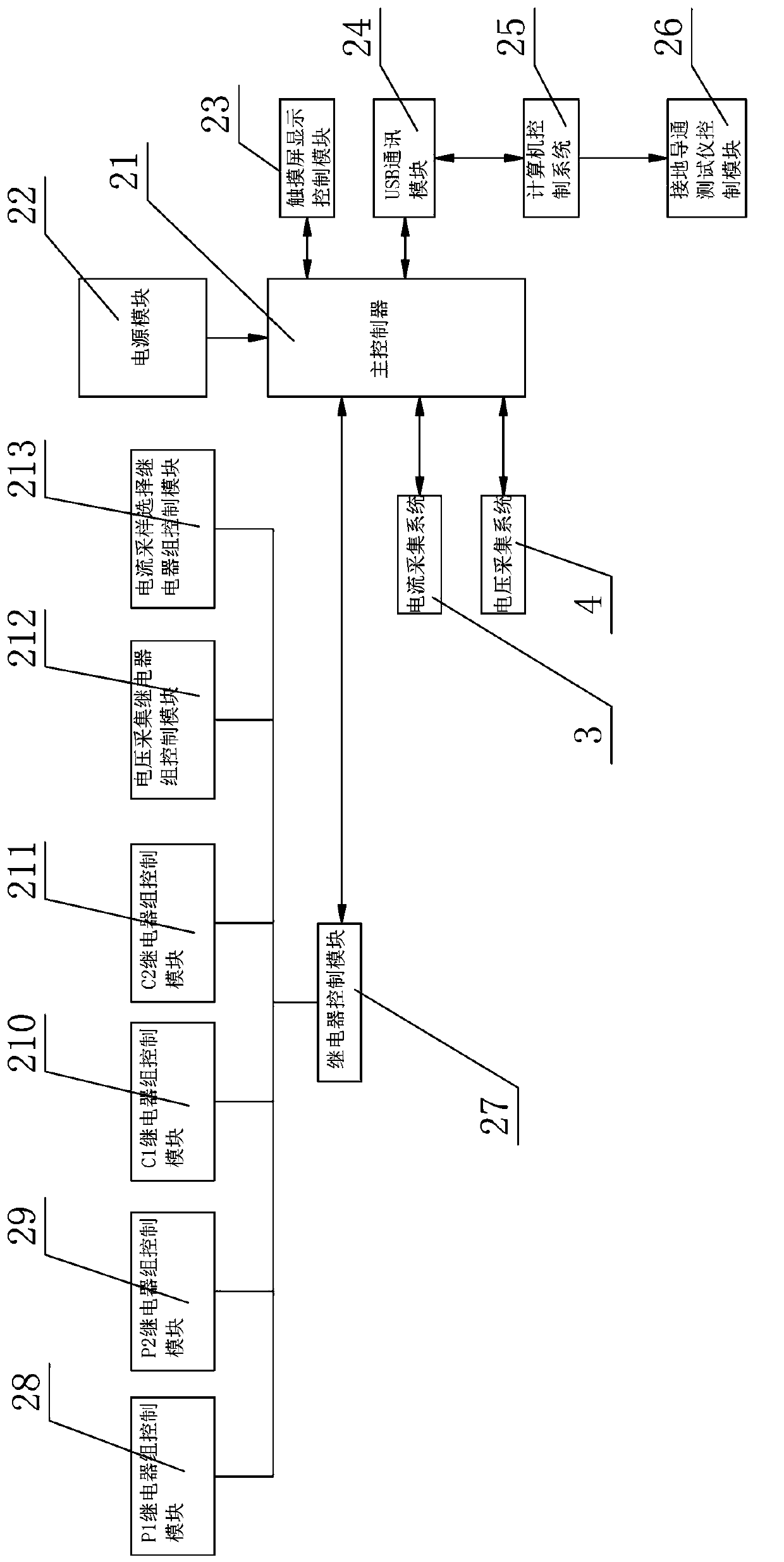
[0032] like figure 1As shown, a calibration system for a ground bond resistance tester includes a housing 1, four terminals and a standard resistance system 6 arranged in the housing 1, a current acquisition system 3, a voltage acquisition system 4, a C1 relay group 14, and a C2 Relay group 7, P1 relay group 15, P2 relay group 8, voltage acquisition relay group 11, current sampling selection relay group 5 and main control system 2, the shell 1 is provided with four terminals, which are respectively C1 terminals , C2 terminal, P1 terminal and P2 terminal, the standard resistance system 6 is electrically connected to the C1 bus 13 through the C1 relay group 14, the C1 bus 13 is connected to the C1 terminal on the shell 1, and the standard resistance system 6 is connected to the C2 relay group 7 Electrically connected with C2 bus 9, C2 bus 9 is connected with C2 terminal on shell 1, standard resistance system 6 is electrically connected with P1 bus 12 through P1 relay group 15, P...

Embodiment 2

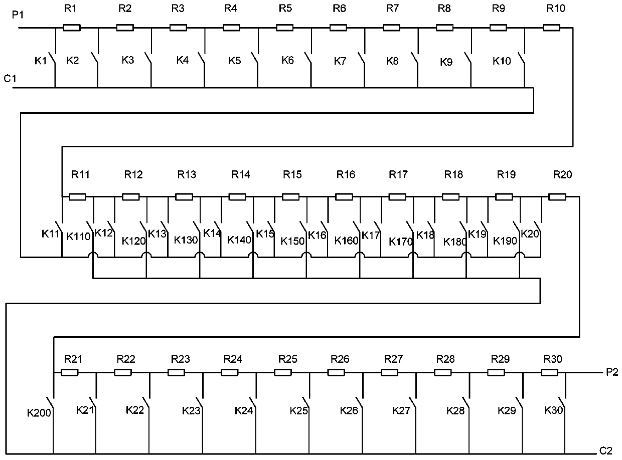
[0063] like Figure 12 As shown, repeating Example 1, there are the following differences: the standard resistor system 6 includes ten 1mΩ standard resistors, ten 10mΩ standard resistors and ten 100mΩ standard resistors, and each standard resistor includes four connection terminals, which are respectively current terminals C1, current terminal C2, potential terminal P1 and potential terminal P2, the potential terminals of all standard resistors are connected in series, and the current terminals of all standard resistors are connected in series to form a standard resistor row, and the potential terminals at both ends of the standard resistor row are respectively connected in series with a relay After that, they are respectively connected to the P1 terminal and the P2 terminal on the shell 1, the current terminal C1 of each standard resistor is connected to a relay and then connected to the C1 bus 13, and the current terminal C2 of each standard resistor is connected to a relay a...


PUM


Abstract

The invention relates to a standard resistance system for correction of a grounding conduction resistance tester. The standard resistance system for correction of the grounding conduction resistance tester comprises a plurality of standard resistors, and each standard resistor comprises four wiring terminals, namely, a current terminal C1, a current terminal C2, an electric potential terminal P1 and an electric potential terminal P2. The electric potential terminals of all the standard resistors are connected in series, the current terminals of all the standard resistors are connected in series, the electric potential terminal P1 of each standard resistor is connected with a P1 relay, the electric potential terminal P2 of each standard resistor is connected with a P2 relay, the current terminal C1 of each standard resistor is connected with a C1 relay, and the current terminal C2 of each standard resistor is connected with a C2 relay. The standard resistance system for correction is formed by adopting the multiple material standard resistors, the number of the standard resistors and resistance value which take part in the correction are controlled through the relays, a grounding onresistance tester is corrected and detected by using the material standard resistors, and the intelligent combination of the material resistors and relay control is flexible and convenient.

Description

Technical field: [0001] The invention belongs to the technical field of detection and calibration of a grounding conduction resistance tester, and in particular relates to a standard resistance system for calibrating a grounding conduction resistance tester. Background technique: [0002] The ground connection resistance tester is used to measure the accessible metal casing and the outlet of the electrical equipment powered by the AC grid (such as household appliances, electric heating appliances, medical electrical equipment and measurement, control and laboratory electrical equipment, etc.) An instrument that measures the on-resistance between the safety ground terminals (lines). By outputting AC or DC current, it is applied between the accessible metal shell of the tested object and the safety ground terminal (line) drawn from the device, and the voltage drop generated by the current flowing through the tested object is measured, and then the voltage and current are passe...

Claims


Application Information

Patent Timeline
Patent Type & Authority Applications(China)
IPC IPC(8): G01R35/00
CPCG01R35/007
Inventor 朱小明周秉时陆新东郭美玉陈兵贾红斌余昊阳陈昊李东波李锦华
Owner HENAN PROVINCE INST OF METROLOGY
Why Eureka
Try Eureka