Butterfly wing microgyroscope using polygonal vibration beam and preparation method thereof
A vibrating beam and polygonal technology, which is applied in the direction of gyroscope/steering sensing equipment, gyro effect for speed measurement, measuring device, etc., can solve the problem of high degree of influence of the azimuth angle of the main axis of the section, weak section tolerance ability, and difficult control of machining errors To achieve good stress release effect, improve structural robustness, and reduce structural stress
- Summary
- Abstract
- Description
- Claims
- Application Information
AI Technical Summary
Problems solved by technology
Method used
Image
Examples
Embodiment 1
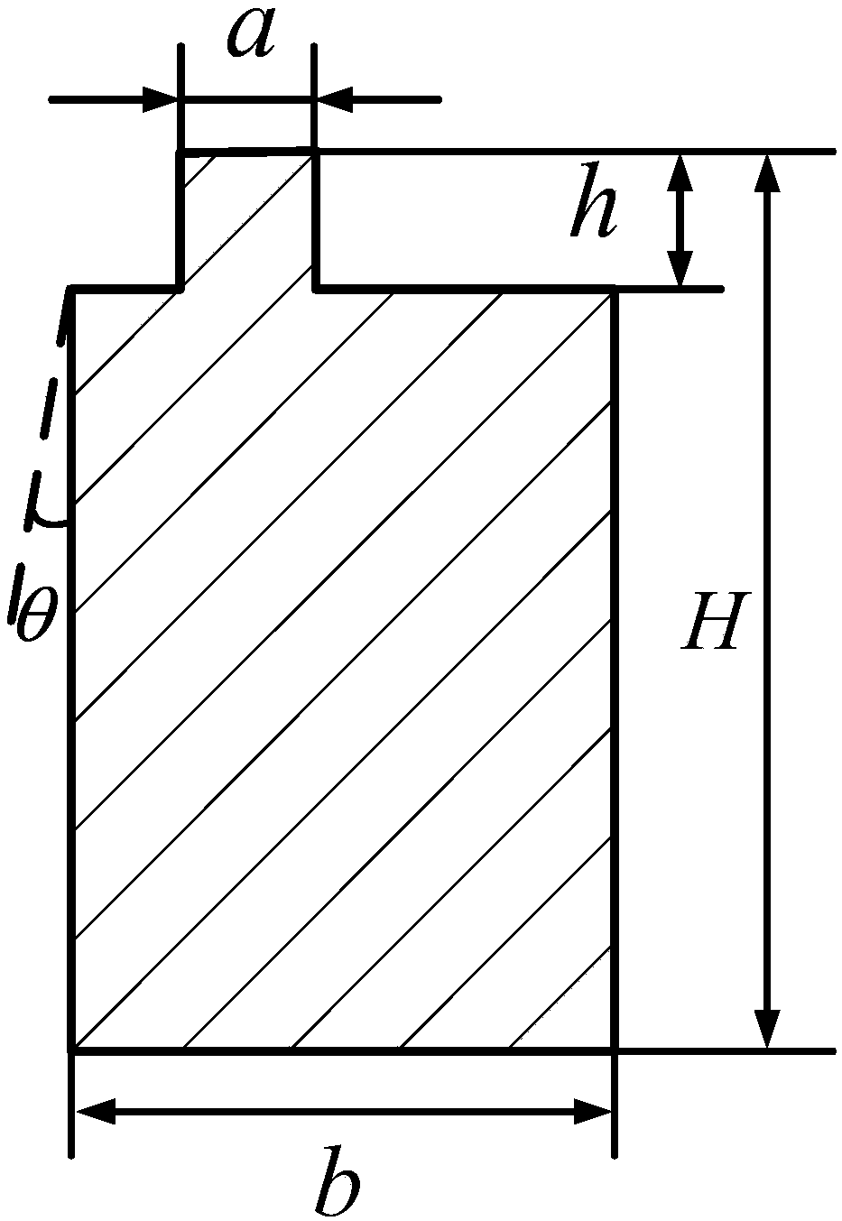
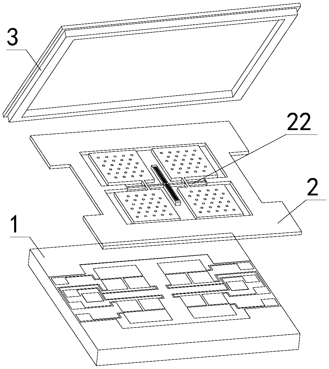
[0050] Such as figure 2 with image 3 As shown, the present embodiment adopts the butterfly-wing micro-gyroscope with polygonal vibrating beams to include a silicon electrode substrate 1, a silicon cover plate 3, and a silicon sensitive structure 2 with a vibrating beam. The vibrating beam of the silicon sensitive structure 2 is used to prepare the silicon sensitive The SOI silicon wafer of structure 2 is a polygonal vibrating beam 22 made of wet etching and dry etching as raw materials, and the azimuth angle of the main axis of the polygonal vibrating beam 22 is not equal to 90°. In the silicon sensitive structure 2 of the butterfly-wing micro-gyroscope, the vibration beam is an important part of the silicon sensitive structure 2. The stiffness of the vibration beam determines the driving and detection modal frequency and the motion characteristics of the vibration beam, and the stiffness of the vibration beam is related to the vibration beam The cross-sectional shape is cl...
Embodiment 2
[0079] This embodiment is basically the same as the first embodiment, the main difference being that the shape of the polygonal vibrating beam 22 is different. Such as Figure 12 As shown, the cross-section of the polygonal vibrating beam 22 in this embodiment is pentagonal, and one end of one side (a side) of the polygonal vibrating beam 22 is respectively provided with an inclined wall a formed by wet etching. 1 , Both ends of the other side (side b) are straight walls b formed by dry etching 1 and b 2 , the other end of side a is a straight wall a formed by dry etching 2 .
Embodiment 3
[0081] This embodiment is basically the same as the first embodiment, the main difference being that the shape of the polygonal vibrating beam 22 is different. Such as Figure 13 As shown, the cross-section of the polygonal vibrating beam 22 in this embodiment is a quadrilateral, the width of one side (side a) of the polygonal vibrating beam 22 is 0, and one end of the side a is respectively provided with a bevel formed by wet etching. wall a 1 , Both ends of the other side (side b) are straight walls b formed by dry etching 1 and b 2 , the other end of side a is a straight wall a formed by dry etching 2 .
PUM
 Abstract
Description
Claims
Application Information
 - Generate Ideas
- Intellectual Property
- Life Sciences
- Materials
- Tech Scout
- Unparalleled Data Quality
- Higher Quality Content
- 60% Fewer Hallucinations
Browse by: Latest US Patents, China's latest patents, Technical Efficacy Thesaurus, Application Domain, Technology Topic, Popular Technical Reports.
© 2025 PatSnap. All rights reserved.Legal|Privacy policy|Modern Slavery Act Transparency Statement|Sitemap|About US| Contact US: help@patsnap.com


