
Composite floor slab and wall connecting joint and construction method thereof

A technology for superimposing floors and connecting nodes, which is applied to floors, building components, buildings, etc., and can solve problems affecting building quality and poor connection stability

Pending Publication Date: 2019-04-05
CHANGSHA BROAD HOMES IND GRP CO LED
View PDF8 Cites 2 Cited by
  • Summary
  • Abstract
  • Description
  • Claims
  • Application Information

AI Technical Summary

Problems solved by technology

[0005] Based on this, it is necessary to solve the problem of poor connection stability between the laminated floor and the wall in the prior art, which affects the quality of the building, and provide a connection node between the laminated floor and the wall that improves the above defects and its construction method

Method used


Image

  • Composite floor slab and wall connecting joint and construction method thereof
  • Composite floor slab and wall connecting joint and construction method thereof

Examples


Embodiment Construction

[0028] In order to facilitate the understanding of the present invention, the present invention will be described more fully below with reference to the associated drawings. Preferred embodiments of the invention are shown in the accompanying drawings. However, the present invention can be embodied in many different forms and is not limited to the embodiments described herein. On the contrary, these embodiments are provided to make the understanding of the disclosure of the present invention more thorough and comprehensive.

[0029] It should be noted that when an element is referred to as being “fixed” to another element, it can be directly on the other element or there can also be an intervening element. When an element is referred to as being "connected to" another element, it can be directly connected to the other element or intervening elements may also be present. The terms "vertical," "horizontal," "left," "right," and similar expressions are used herein for purposes ...


PUM


Abstract

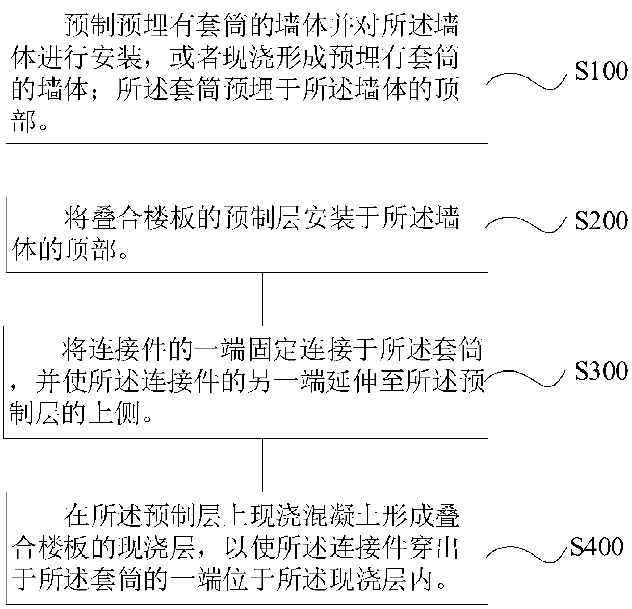
The invention relates to a composite floor slab and wall connecting joint and a construction method thereof. The composite floor slab and wall connecting joint comprises composite floor slabs, a walland a connecting assembly; each composite floor slab comprises a prefabricated layer and a cast-in-place layer located on the prefabricated layer; one end of the prefabricated layer is supported on the top of the wall; the connecting assembly comprises a sleeve and a connecting piece, the sleeve is embedded at the top of the wall, one end of the connecting piece penetrates into the sleeve and is fixedly connected with the sleeve, and the other end of the connecting piece extends to the cast-in-place layer of the composite floor slab. According to the composite floor slab and wall connecting joint, the connecting pieces embedded at the cast-in-place layers of the composite floor slabs are fixedly connected with the sleeve embedded at the top of the wall so as to achieve fixed connection ofthe wall and the composite floor slabs, and therefore the problem that in the prior art, concrete needs to be poured into a cast-in-place hole with the small space, so that connection between the walland reinforcing steel ribs is not stable is avoided.

Description

technical field [0001] The invention relates to the technical field of prefabricated building construction, in particular to a connection node between an inner wall body and a laminated floor slab and a construction method thereof. Background technique [0002] The prefabricated building is a building assembled on the construction site with prefabricated components. Since the prefabricated components are made in advance according to the market and user needs, it has the advantages of fast construction speed, low cost, less affected by climate and weather, labor saving, and reduced construction site. A series of advantages such as reducing the workload and complexity and improving the quality of the building. At present, prefabricated buildings are more and more used in the construction of my country's construction projects. [0003] The laminated slab is an assembled monolithic slab formed by laminating prefabricated layers and cast-in-place reinforced concrete layers. The...

Claims


Application Information

Patent Timeline
IPC IPC(8): E04B5/17E04B5/00
CPCE04B5/00E04B5/17
Inventor 张剑唐芬谭新明龙坪峰李志宏朱换良
Owner CHANGSHA BROAD HOMES IND GRP CO LED
Learn More