
Method for operating a waste heat steam generator

A technology of waste heat steam and generator, applied in steam generation, feed water heater, preheating, etc., to achieve the effect of improving flexibility

Active Publication Date: 2021-06-25
SIEMWNS ENERGY GLOBAL GMBH & CO KG
View PDF4 Cites 0 Cited by
  • Summary
  • Abstract
  • Description
  • Claims
  • Application Information

AI Technical Summary

Problems solved by technology

[0003] During the regulation or control of the feed water rate of waste heat steam generators designed according to the forced flow principle, it has been found that using only known methods (for example from WO2009 / 150055A2), the flow medium leaving the evaporator cannot always be avoided in an optimal manner. Load-dependent unsteady-state temperature fluctuations

Method used


Image

  • Method for operating a waste heat steam generator
  • Method for operating a waste heat steam generator
  • Method for operating a waste heat steam generator

Examples


Embodiment Construction

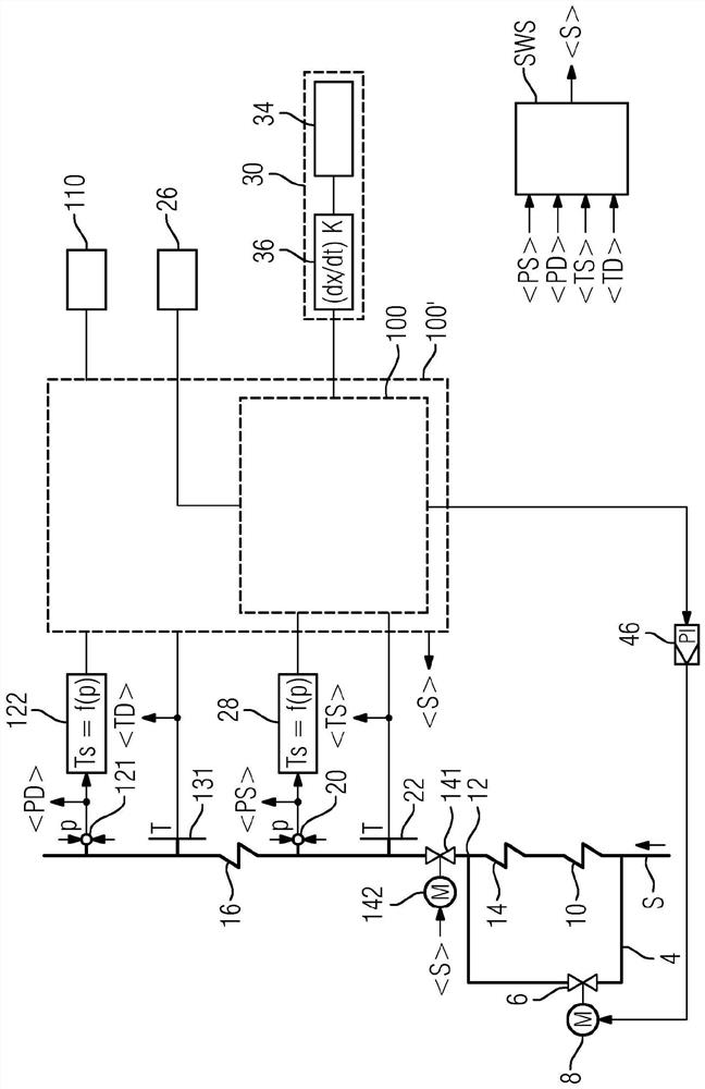
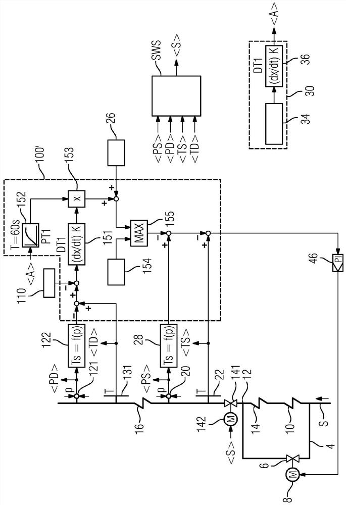
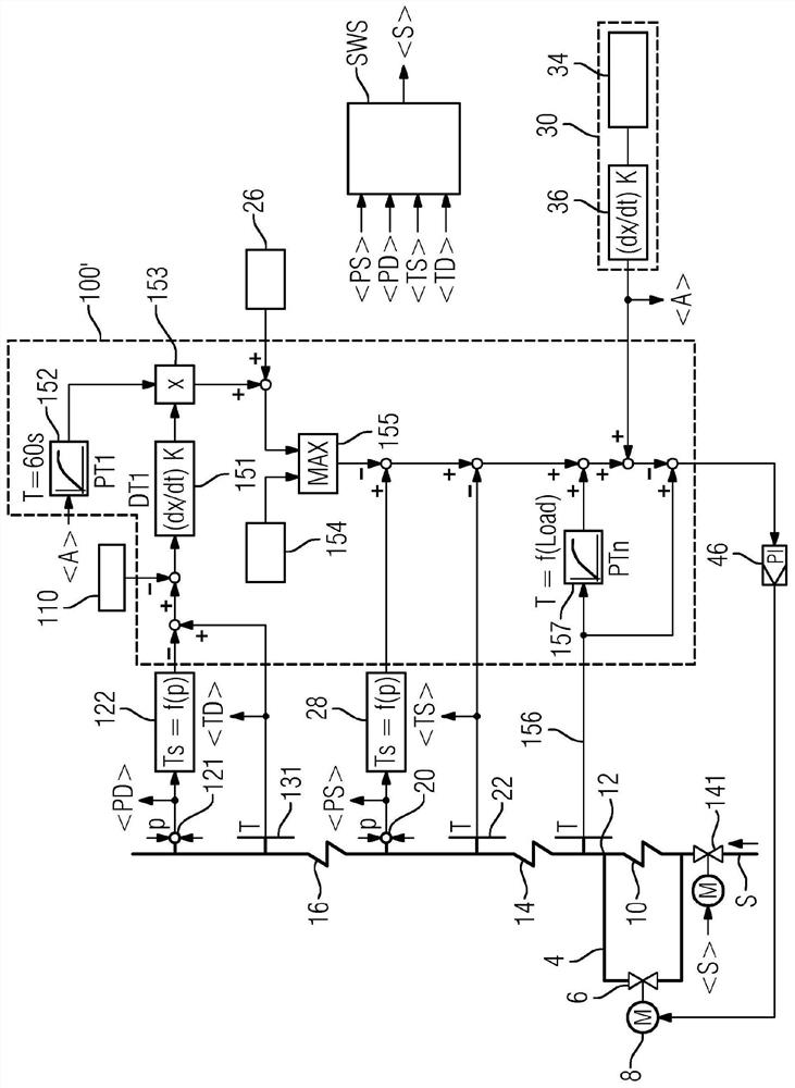
[0012] figure 1 First, a first configuration of the waste heat steam generator that can be adjusted is schematically shown. The flow medium S driven by a pump (not specifically shown) first flows into the first preheater heating surface or economizer heating surface 10 . However, the bypass line 4 has previously branched. In order to regulate the flow rate of the bypass line 4 a flow control valve 6 adjustable by a controllable motor 8 is provided. Simple control valves can also be provided, however, the subcooling at the evaporator inlet can be better regulated by means of fast-acting control valves. Thus, depending on the position of the flow control valve 6 , part of the flow medium S flows into the bypass line 4 , another part of the flow medium S flows through the first economizer heating surface 10 and then through the other economizer heating surface 14 . In the present design, at the outlet of the economizer heated surface 14 , the flow medium from the bypass line 4...


PUM


Abstract

The invention relates to a method of operating a waste heat steam generator, in particular a method for operating a waste heat steam generator designed according to the forced flow principle, comprising: an evaporator (16) through which a flow medium flows; energy saving with a plurality of economizer heating surfaces (10, 14); and on the flow medium side with a bypass line (4) connected in parallel to the plurality of economizer heating surfaces (10, 14). In this method, the variable (30), the variable (30) characterizing the thermal energy supplied to the waste heat steam generator (1), is used to control or regulate the flow rate of the bypass line (4), wherein the flow medium passes through the bypass line Regulation or control of the flow rate of (4) occurs at the inlet of the evaporator (16), which is influenced by the subcooling target value (26). Regulation or control of the flow rate of the flow medium through the bypass line (4) also takes place at the outlet of the evaporator (16), which is influenced by the superheat target value (110).

Description

technical field [0001] The invention relates to a method for operating a waste heat steam generator as described herein, in particular to a load-dependent control of a waste heat steam generator designed according to the forced flow principle. Background technique [0002] EP2224164A1 discloses a method for operating a waste heat steam generator comprising an evaporator; an economizer with multiple economizer heating surfaces; and a bypass line heated with the multiple economizers on the flow medium side Surfaces are connected in parallel. In order to increase the operational safety and reliability of waste heat steam generators, a method is disclosed here with which, under all load conditions, the formation of a water-steam mixture at the inlet to the evaporator can be reliably avoided. To this end, a variable characterizing the thermal energy supplied to the waste heat steam generator is provided, which variable is used to control or regulate the flow rate of the bypass l...

Claims


Application Information

Patent Timeline
Patent Type & Authority Patents(China)
IPC IPC(8): F22D1/12F22D5/00
CPCF22D1/12F22D5/00F22D5/34F24D2200/16
Inventor J·布鲁克纳F·托马斯
Owner SIEMWNS ENERGY GLOBAL GMBH & CO KG
Learn More