
Electrofusion bending pipe fittings and its post-firing process

A technology for pipe bending and wire routing, which is applied in the direction of pipe connection layout, pipe/pipe joint/pipe fittings, mechanical equipment, etc. It can solve the problems of electric heating wire fusing, failure to realize pipe fitting welding, etc., and achieve the effect of reducing the probability of being blown.

Inactive Publication Date: 2021-01-05
孙志强
View PDF1 Cites 0 Cited by
  • Summary
  • Abstract
  • Description
  • Claims
  • Application Information

AI Technical Summary

Problems solved by technology

[0004] However, with the above method, when the bending pipe fittings are energized to make the electric heating wires heat and electrofusion weld, it is easy to fuse the twisted electric heating wires together. During use, there is often a problem that the welding between the pipe fittings cannot be realized due to the electric heating wires being blown.

Method used


Image

  • Electrofusion bending pipe fittings and its post-firing process
  • Electrofusion bending pipe fittings and its post-firing process
  • Electrofusion bending pipe fittings and its post-firing process

Examples


Embodiment

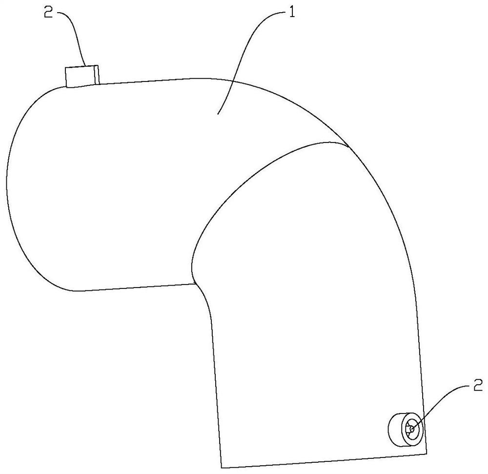
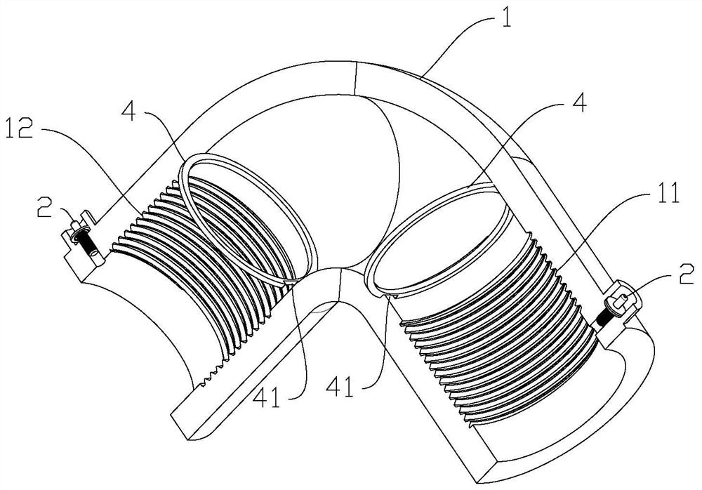
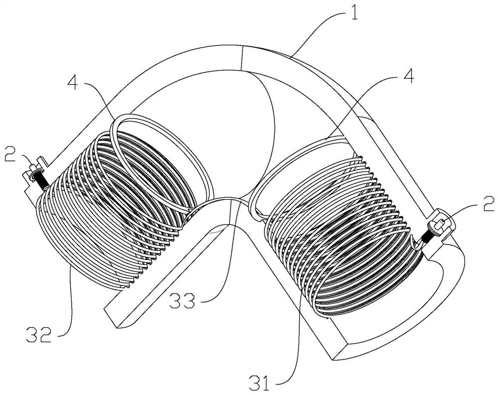
[0028] Electrofusion bending pipe fitting 1, first refer to the attached figure 1 , is the overall appearance diagram of the electrofusion pipe bend 1, wherein the two ends of the bend pipe 1 are respectively provided with conductive terminals 2, continue to refer to the attached figure 2 and 3 , the first wire slot 11 and the second wire slot 12 are respectively provided at both ends of the elbow piece 1 for embedding the first heating wire loop 31 and the second heating wire loop 32, and the two ends of the elbow piece 1 are close to the bend Valve cavity gear rings 4 are provided at all places, and a relief groove 41 is provided between the valve cavity gear ring 4 and the pipe wall to facilitate the passage of the bridging heating wire 33 connecting the first wire groove 11 and the second wire groove 12, and The first heating wire, the bridging heating wire 33 and the second heating wire are all arranged through a continuous heating wire, and here the relief groove 41 is...


PUM


Abstract

The invention discloses an electric melting bent pipe fitting. The electric melting bent pipe fitting comprises a bent pipe fitting body and further comprises a first electric heating wire ring and asecond electric heating wire ring which are embedded in inner pipe walls of the two ends of the bent pipe fitting body; the first electric heating wire ring and the second electric heating wire ring are mutually connected through a bridging electric heating wire; and the first electric heating wire ring, the second electric heating wire ring and the bridging electric heating wire are continuouslyarranged through an electric heating wire. Compared with the problem that two sections of electric heating wire rings in an existing bent pipe fitting are in twist joint and consequently are prone tobeing fused, the electric heating wire in the bent pipe fitting is continuously laid overall, and after powering-on, the fusing probability of the electric heating wire is greatly lowered.

Description

technical field [0001] The invention relates to the field of plastic pipe fittings, in particular to an electric melting bending pipe fitting and its post-firing process. Background technique [0002] PE electric fusion pipe fittings are divided into exposed wire electric fusion pipe fittings, plastic-coated wire electric fusion pipe fittings and rear cloth wire electric fusion pipe fittings. The three processes have their own advantages. The electric fusion interface of the exposed wire electric fusion pipe fittings under the same conditions, its The peel strength and welding operation error tolerance are slightly better than the electric fusion pipe fittings produced by other processes, and the connection of the plastic-coated wire electric fusion pipe fittings on the steel mesh skeleton PE pipe has unique advantages. Wire electrofusion pipe fittings, which are made of injection molded pipe blanks after turning and embedding wires, so the dimensional accuracy cannot be ach...

Claims


Application Information

Patent Timeline
Patent Type & Authority Patents(China)
IPC IPC(8): F16L47/03
CPCF16L47/03
Inventor 孙志强
Owner 孙志强
Learn More