A narrow-band microwave response material and its preparation method
A frequency and microwave technology, applied in the field of narrow-band microwave responsive materials and their preparation, to achieve the effect of simple process
- Summary
- Abstract
- Description
- Claims
- Application Information
AI Technical Summary
Problems solved by technology
Method used
Image
Examples
Embodiment 1
[0036] The preparation method of microwave response material sample 1 of the present invention comprises the following steps:
[0037] Step 1: disperse silver nanofibers in methanol under the assistance of ultrasound to prepare a 1 g / L dispersion; prepare a 1 mol / L zinc nitrate methanol solution; prepare a 1 mol / L imidazole methanol solution. Add 20 ml of zinc nitrate solution to 80 ml of silver nanofiber dispersion and stir for more than 30 minutes, then add 100 ml of methylimidazole solution and stir for 12 hours, and obtain the silver / metal organic framework before filtering, washing with methanol, and vacuum drying. body.
[0038] In step 2, the silver / metal organic framework precursor was placed under argon gas and heated to 600°C and then calcined at 600°C for 4 hours to obtain sample 1. Wherein, the heating rate is 5 degrees / min.
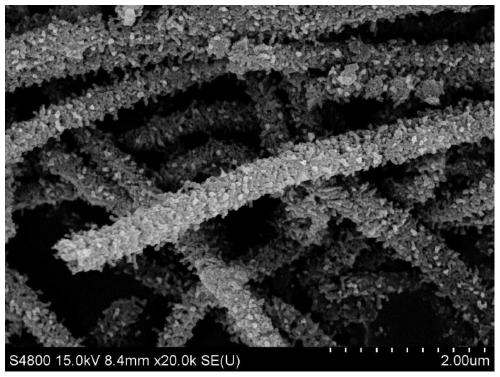
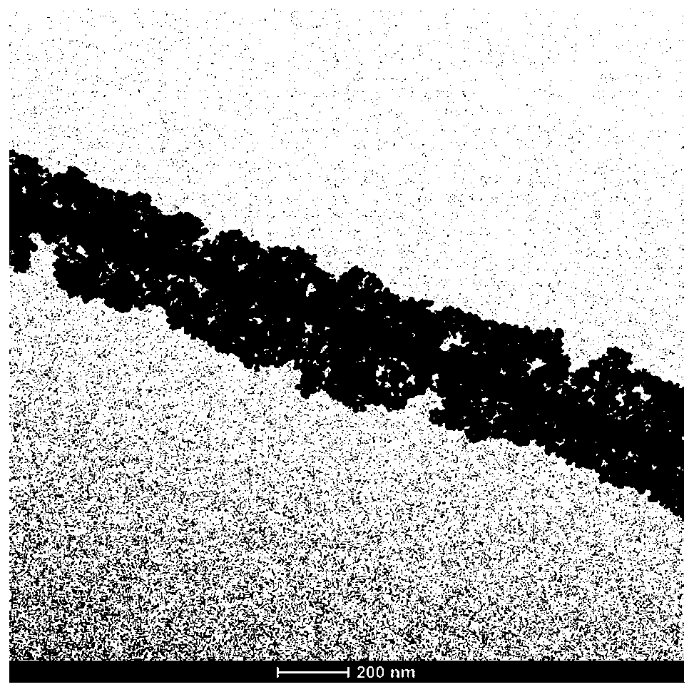
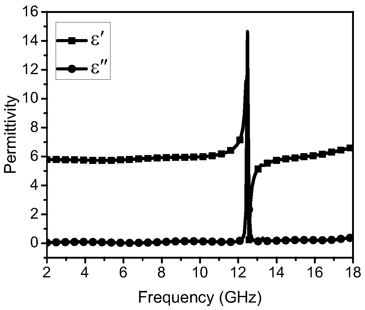
[0039] figure 1 and figure 2 They are the scanning electron microscope images and transmission electron microscope images of sample 1 i...
Embodiment 2
[0041] Change the zinc nitrate solution of step 1 in embodiment 1 into cobalt chloride solution, other implementation conditions are the same as embodiment 1, obtain sample 2.
[0042] Figure 5 and Figure 6 The scanning electron micrographs and transmission electron micrographs of sample 2 in Example 2 are respectively. It can be seen that sample 2 has a uniform core-shell nanofiber structure microscopically, has a high aspect ratio, and has a shell thickness of about 60 nanometers. Figure 7 and Figure 8 It is the complex permittivity diagram and complex permeability diagram of sample 2 microwave frequency band in embodiment 2, it can be seen that sample 2 shows weak dielectric resonance phenomenon in multiple frequency bands such as 10.35, 11.00 and 16.57 GHz, and at 10.52 The two frequencies of 16.27 GHz and 16.27 GHz exhibit weak magnetic resonance characteristics.
Embodiment 3
[0044] Change the zinc nitrate solution of step 1 in embodiment 1 into the mixed solution of zinc nitrate and cobalt chloride that the molar ratio is 1: 1, other implementation conditions are the same as embodiment 1, obtain sample 3.
[0045] Figure 9 and Figure 10 They are the scanning electron microscope images and transmission electron microscope images of sample 3 in Example 3, respectively. It can be seen that sample 3 presents microscopically uniform rough nanofibers, has a high aspect ratio and a core-shell nanostructure, and the shell thickness is about 50 Nano. Figure 11 and Figure 12 It is the complex permittivity diagram and the complex permeability diagram of sample 3 microwave frequency band in embodiment 3, it can be seen that sample 3 shows a narrow-band dielectric resonance phenomenon that is stronger than sample 1 at 14.48 GHz, and shows a ratio of 14.52 GHz. The enhanced narrow-band magnetic resonance phenomenon of sample 1 fully demonstrates that cob...
PUM
| Property | Measurement | Unit |
|---|---|---|
| thickness | aaaaa | aaaaa |
| concentration | aaaaa | aaaaa |
| thickness | aaaaa | aaaaa |
Abstract
Description
Claims
Application Information
 - R&D
- Intellectual Property
- Life Sciences
- Materials
- Tech Scout
- Unparalleled Data Quality
- Higher Quality Content
- 60% Fewer Hallucinations
Browse by: Latest US Patents, China's latest patents, Technical Efficacy Thesaurus, Application Domain, Technology Topic, Popular Technical Reports.
© 2025 PatSnap. All rights reserved.Legal|Privacy policy|Modern Slavery Act Transparency Statement|Sitemap|About US| Contact US: help@patsnap.com


